 Package Modelica.Electrical.Digital.Sources
Time-dependent digital signal sources
 Package Modelica.Electrical.Digital.Sources
The sources are not taken from Standard Logic. They were added since they turned out to be quite useful, since such sources are often needed. For a better optical overview the colour green was chosen for the sources.
Extends from Modelica.Icons.SourcesPackage (Icon for packages containing sources).
| Name | Description |
|---|---|
Clock | Digital Clock Source |
Pulse | Digital Pulse Source |
Set | Digital Set Source |
Step | Digital Step Source |
Table | Digital Tabular Source |
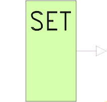 Block Modelica.Electrical.Digital.Sources.Set
Sets a nine valued digital signal, which is specified by the setval parameter.
To specify setval, the integer code has to be used.
Code Table
| Logic value | Integer code | Meaning |
| 'U' | 1 | Uninitialized |
| 'X' | 2 | Forcing Unknown |
| '0' | 3 | Forcing 0 |
| '1' | 4 | Forcing 1 |
| 'Z' | 5 | High Impedance |
| 'W' | 6 | Weak Unknown |
| 'L' | 7 | Weak 0 |
| 'H' | 8 | Weak 1 |
| '-' | 9 | Do not care |
If the logic values are imported by
import L = Digital.Interfaces.Logic;
they can be used to specify the parameter, e.g., L.'0' for forcing 0.
| Type | Name | Default | Description |
|---|---|---|---|
Logic | x | Logic value to be set |
| Type | Name | Description |
|---|---|---|
output DigitalOutput | y |
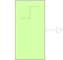 Block Modelica.Electrical.Digital.Sources.Step
The step source output signal steps from the value before to the value after at the time stepTime.
To specify the logic value parameters, the integer code has to be used.
Code Table
| Logic value | Integer code | Meaning |
| 'U' | 1 | Uninitialized |
| 'X' | 2 | Forcing Unknown |
| '0' | 3 | Forcing 0 |
| '1' | 4 | Forcing 1 |
| 'Z' | 5 | High Impedance |
| 'W' | 6 | Weak Unknown |
| 'L' | 7 | Weak 0 |
| 'H' | 8 | Weak 1 |
| '-' | 9 | Do not care |
If the logic values are imported by
import L = Digital.Interfaces.Logic;
they can be used to specify the parameter, e.g., L.'0' for forcing 0.
| Type | Name | Default | Description |
|---|---|---|---|
Logic | before | Logic value before step | |
Logic | after | Logic value after step | |
Real | stepTime | step time |
| Type | Name | Description |
|---|---|---|
output DigitalOutput | y |
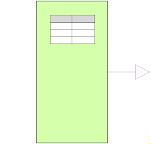 Block Modelica.Electrical.Digital.Sources.Table
The table source output signal y steps to the values of the x table at the corresponding
timepoints in the t table.
The initial value is specified by y0.
To specify the logic value parameters, the integer code has to be used.
Code Table
| Logic value | Integer code | Meaning |
| 'U' | 1 | Uninitialized |
| 'X' | 2 | Forcing Unknown |
| '0' | 3 | Forcing 0 |
| '1' | 4 | Forcing 1 |
| 'Z' | 5 | High Impedance |
| 'W' | 6 | Weak Unknown |
| 'L' | 7 | Weak 0 |
| 'H' | 8 | Weak 1 |
| '-' | 9 | Do not care |
If the logic values are imported by
import L = Digital.Interfaces.Logic;
they can be used to specify the parameter, e.g., L.'0' for forcing 0.
| Type | Name | Default | Description |
|---|---|---|---|
Logic | x[:] | {L.'1'} | vector of values |
Real | t[size(x, 1)] | {1} | vector of corresponding time points |
Logic | y0 | L.'U' | initial output value |
final Integer | n | size(x, 1) | table size |
| Type | Name | Description |
|---|---|---|
output DigitalOutput | y |
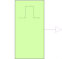 Model Modelica.Electrical.Digital.Sources.Pulse
The pulse source forms pulses between the quiet value and the pulse value. The pulse length width is specified in percent of the period length period. The number of periods is specified by nperiod. If nperiod is less than zero, the number of periods is unlimited.
To specify the logic value parameters, the integer code has to be used.
Code Table
| Logic value | Integer code | Meaning |
| 'U' | 1 | Uninitialized |
| 'X' | 2 | Forcing Unknown |
| '0' | 3 | Forcing 0 |
| '1' | 4 | Forcing 1 |
| 'Z' | 5 | High Impedance |
| 'W' | 6 | Weak Unknown |
| 'L' | 7 | Weak 0 |
| 'H' | 8 | Weak 1 |
| '-' | 9 | Do not care |
If the logic values are imported by
import L = Digital.Interfaces.Logic;
they can be used to specify the parameter, e.g., L.'0' for forcing 0.
| Type | Name | Default | Description |
|---|---|---|---|
Real | width | Widths of pulses in % of periods | |
Time | period | Time for one period | |
Time | startTime | Output = quiet for time < startTime | |
Logic | pulse | pulsed value | |
Logic | quiet | quiet value | |
Integer | nperiod | Number of periods (< 0 means infinite number of periods) |
| Type | Name | Description |
|---|---|---|
output DigitalOutput | y |
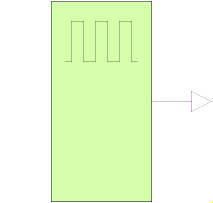 Model Modelica.Electrical.Digital.Sources.Clock
The clock source forms pulses between the '0' value (forcing 0) and the '1' value (forcing 1). The pulse length width is specified in percent of the period length period. The number of periods is unlimited. The first pulse starts at startTime.
The clock source is a special but often used variant of the pulse source.
| Type | Name | Default | Description |
|---|---|---|---|
Time | startTime | Output = offset for time < startTime | |
Time | period | Time for one period | |
Real | width | Width of pulses in % of period |
| Type | Name | Description |
|---|---|---|
output DigitalOutput | y | Connector of Digital output signal |