 Package Modelica.Blocks.Discrete
Library of discrete input/output blocks with fixed sample period
Package Modelica.Blocks.Discrete
This package contains discrete control blocks with fixed sample period. Every component of this package is structured in the following way:
A sampled data system may consist of components of package Discrete and of every other purely algebraic input/output block, such as the components of packages Modelica.Blocks.Math, Modelica.Blocks.Nonlinear or Modelica.Blocks.Sources.
Extends from Modelica.Icons.Package (Icon for standard packages).
| Name | Description |
|---|---|
FirstOrderHold | First order hold of a sampled-data system |
Sampler | Ideal sampling of continuous signals |
StateSpace | Discrete State Space block |
TransferFunction | Discrete Transfer Function block |
TriggeredMax | Compute maximum, absolute value of continuous signal at trigger instants |
TriggeredSampler | Triggered sampling of continuous signals |
UnitDelay | Unit Delay Block |
ZeroOrderHold | Zero order hold of a sampled-data system |
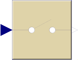 Block Modelica.Blocks.Discrete.Sampler
Samples the continues input signal with a sampling rate defined via parameter samplePeriod.
Extends from Modelica.Blocks.Interfaces.DiscreteSISO (Single Input Single Output discrete control block).
| Type | Name | Default | Description |
|---|---|---|---|
Time | samplePeriod | Sample period of component | |
Time | startTime | 0 | First sample time instant |
| Type | Name | Description |
|---|---|---|
input RealInput | u | Connector of Real input signal |
output RealOutput | y | Connector of Real output signal |
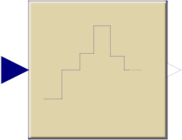 Block Modelica.Blocks.Discrete.ZeroOrderHold
The output is identical to the sampled input signal at sample time instants and holds the output at the value of the last sample instant during the sample points.
Extends from Modelica.Blocks.Interfaces.DiscreteSISO (Single Input Single Output discrete control block).
| Type | Name | Default | Description |
|---|---|---|---|
Time | samplePeriod | Sample period of component | |
Time | startTime | 0 | First sample time instant |
| Type | Name | Description |
|---|---|---|
input RealInput | u | Connector of Real input signal |
output RealOutput | y | Connector of Real output signal |
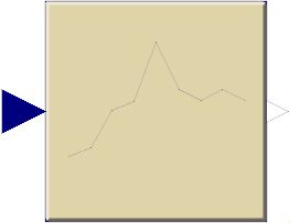 Block Modelica.Blocks.Discrete.FirstOrderHold
The output signal is the extrapolation through the values of the last two sampled input signals.
Extends from Modelica.Blocks.Interfaces.DiscreteSISO (Single Input Single Output discrete control block).
| Type | Name | Default | Description |
|---|---|---|---|
Time | samplePeriod | Sample period of component | |
Time | startTime | 0 | First sample time instant |
| Type | Name | Description |
|---|---|---|
input RealInput | u | Connector of Real input signal |
output RealOutput | y | Connector of Real output signal |
 Block Modelica.Blocks.Discrete.UnitDelay
This block describes a unit delay:
          1
     y = --- * u
          z
that is, the output signal y is the input signal u of the previous sample instant. Before the second sample instant, the output y is identical to parameter yStart.
Extends from Modelica.Blocks.Interfaces.DiscreteSISO (Single Input Single Output discrete control block).
| Type | Name | Default | Description |
|---|---|---|---|
Real | y_start | 0 | Initial value of output signal |
Time | samplePeriod | Sample period of component | |
Time | startTime | 0 | First sample time instant |
| Type | Name | Description |
|---|---|---|
input RealInput | u | Connector of Real input signal |
output RealOutput | y | Connector of Real output signal |
The discrete transfer function block defines the transfer function between the input signal u and the output signal y. The numerator has the order nb-1, the denominator has the order na-1.
          b(1)*z^(nb-1) + b(2)*z^(nb-2) + ... + b(nb)
   y(z) = -------------------------------------------- * u(z)
          a(1)*z^(na-1) + a(2)*z^(na-2) + ... + a(na)
State variables x are defined according to controller canonical form. Initial values of the states can be set as start values of x.
Example:
Blocks.Discrete.TransferFunction g(b = {2,4}, a = {1,3});
results in the following transfer function:
        2*z + 4
   y = --------- * u
         z + 3
Extends from Modelica.Blocks.Interfaces.DiscreteSISO (Single Input Single Output discrete control block).
| Type | Name | Default | Description |
|---|---|---|---|
Real | b[:] | {1} | Numerator coefficients of transfer function. |
Real | a[:] | {1} | Denominator coefficients of transfer function. |
Time | samplePeriod | Sample period of component | |
Time | startTime | 0 | First sample time instant |
| Type | Name | Description |
|---|---|---|
input RealInput | u | Connector of Real input signal |
output RealOutput | y | Connector of Real output signal |
 Block Modelica.Blocks.Discrete.StateSpace
The discrete state space block defines the relation between the input u and the output y in state space form:
    x = A * pre(x) + B * u
    y = C * pre(x) + D * u
where pre(x) is the value of the discrete state x at the previous sample time instant. The input is a vector of length nu, the output is a vector of length ny and nx is the number of states. Accordingly
        A has the dimension: A(nx,nx),
        B has the dimension: B(nx,nu),
        C has the dimension: C(ny,nx),
        D has the dimension: D(ny,nu)
Example:
     parameter: A = [0.12, 2;3, 1.5]
     parameter: B = [2, 7;3, 1]
     parameter: C = [0.1, 2]
     parameter: D = zeros(ny,nu)

results in the following equations:
  [x[1]]   [0.12  2.00] [pre(x[1])]   [2.0  7.0] [u[1]]
  [    ] = [          ]*[         ] + [        ]*[    ]
  [x[2]]   [3.00  1.50] [pre(x[2])]   [0.1  2.0] [u[2]]
                             [pre(x[1])]            [u[1]]
       y[1]   = [0.1  2.0] * [         ] + [0  0] * [    ]
                             [pre(x[2])]            [u[2]]
Extends from Modelica.Blocks.Interfaces.DiscreteMIMO (Multiple Input Multiple Output discrete control block).
| Type | Name | Default | Description |
|---|---|---|---|
Real | A[:,size(A, 1)] | [1,0; 0,1] | Matrix A of state space model |
Real | B[size(A, 1),:] | [1; 1] | Matrix B of state space model |
Real | C[:,size(A, 1)] | [1,1] | Matrix C of state space model |
Real | D[size(C, 1),size(B, 2)] | zeros(size(C, 1), size(B, 2)) | Matrix D of state space model |
Time | samplePeriod | Sample period of component | |
Time | startTime | 0 | First sample time instant |
final Integer | nin | size(B, 2) | Number of inputs |
final Integer | nout | size(C, 1) | Number of outputs |
| Type | Name | Description |
|---|---|---|
input RealInput | u[nin] | Connector of Real input signals |
output RealOutput | y[nout] | Connector of Real output signals |
 Block Modelica.Blocks.Discrete.TriggeredSampler
Samples the continuous input signal whenever the trigger input signal is rising (i.e., trigger changes from false to true) and provides the sampled input signal as output. Before the first sampling, the output signal is equal to the initial value defined via parameter y0.
Extends from Modelica.Blocks.Icons.DiscreteBlock (Graphical layout of discrete block component icon).
| Type | Name | Default | Description |
|---|---|---|---|
Real | y_start | 0 | initial value of output signal |
| Type | Name | Description |
|---|---|---|
input RealInput | u | Connector with a Real input signal |
output RealOutput | y | Connector with a Real output signal |
input BooleanInput | trigger |
 Block Modelica.Blocks.Discrete.TriggeredMax
Samples the continuous input signal whenever the trigger input signal is rising (i.e., trigger changes from false to true). The maximum, absolute value of the input signal at the sampling point is provided as output signal.
Extends from Modelica.Blocks.Icons.DiscreteBlock (Graphical layout of discrete block component icon).
| Type | Name | Description |
|---|---|---|
input RealInput | u | Connector with a Real input signal |
output RealOutput | y | Connector with a Real output signal |
input BooleanInput | trigger |