Add
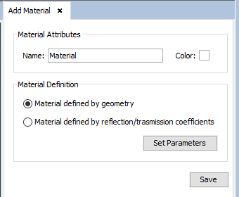
Select the required parameters and click on Save. When clicking on "save" to save the material, if it exists, then a message is displayed informing the user that the material has already been defined. If not, then the material definitions are saved.
In the Add Material window, the following options are available:
Material Attributes - Name. The user specifies the desired name for the new material.
Material Attributes - Color. For more information, see APPENDIX A: Color Selection.
- Constant
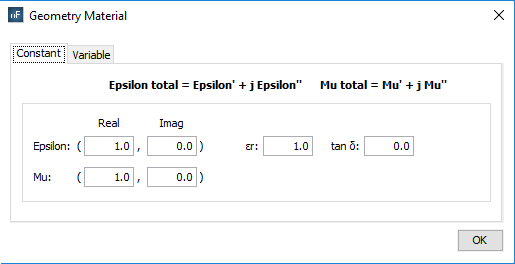
Figure 2. Material defined by geometry, tab ‘Constant’
To set the material properties invariable. Epsilon (e’) and Mu (µ’) are defined with the same restrictions.
§ Real part: common values are greater than or equal to 1.0.
§ Imaginary part: if the imaginary part is negative, the material is considered to have losses; otherwise it would be equivalent to a material with gain.
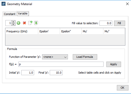
To assign the physical properties of the material according to the frequency.
§ Frequency (in GHz): Sets the associated frequency to the physical properties. The frequency values for each material are interpolated when the simulation is launched in order to use the most suitable one for the working frequency.
§ Real part (’): common values are greater than or equal to 1.0.

§ Add: to add new frequencies to the material properties.
§ Remove: to remove existing frequencies to the material properties


§ Fill value to selection: This option allows the user to automatically change the value of the selected cells of the table with the inserted value
These parameters can also be set using formulas in function of the frequency values.

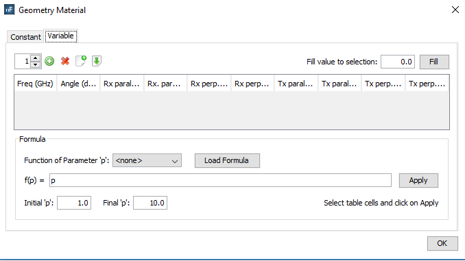
This option serves for completing the selected cells of the table with values depending on the selected function. After choosing the function that we want to apply, pressing the Load Formula button will load the formula f(p) in the field. The next step is choosing the initial and the final value for the function. The final step is selecting the cells that we want to apply the function to and press the button Apply. The cells will be auto-completed with the values created by the chosen function starting with the initial value and ending with the final one.
- Constant
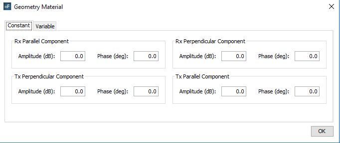
Figure 5. Material defined by coefficient, tab ‘Constant’
- Variable with frequency and angle
Figure 6. Variable with frequency and angle
To assign the refraction and transmission properties of the material according to the frequency and angle.
§ Frequency (in GHz): Sets the associated frequency to the physical properties. The frequency values for each material are interpolated when the simulation is launched in order to use the most suitable one for the working frequency.
§ Angle (in degrees): Sets the associated angle to the physical properties.
