
Composite Properties
Composites may be modeled with solid or shell element. Depending on the element type, the following properties can be used in Radioss to model a composite.
Shell Elements
- Layer-based modeling with /PROP/TYPE10 (SH_COMP), /PROP/TYPE11 (SH_SANDW)
- Ply-based modeling with /PROP/TYPE17 (STACK),
/PROP/TYPE51,
/PROP/PCOMPP+/STACK,
/PROP/TYPE19 (PLY) and /PLY
Figure 1. 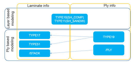
- Layer (ply) number and integration points each layer (ply)
- Anisotropy in layer (ply)
- Layer (ply) thickness and position
- Composite material used for Layer (ply)
Table 1. Layer-based Properties /PROP/TYPE10 (SH_COMP) /PROP/TYPE11 (SH_SANDW) Layer Numbers
Or Pply_IDi
Ply Numbers
=0~100 =1~100 Integration points of each layer/ply 1 per Layer 1 per Layer Iint Integration formulation
Anisotropic direction
√ √ + skew Anisotropic direction
√ Ply orientation change
Angle between anisotropic axis
Layer/Ply thickness
√ Ipos + Layer/Ply position
√ Ipos=2,3,4 Layer/Ply offset
mat_IDi Material for each layer/ply
Use material defined in /PART √ Must use same material type for all layers.
Commonly used Composite Material Law 15, 25 and user material 15, 25 and user material XFEM compatibility (crack propagation) √ With /FAIL/JOHNSON, /FAIL/TAB1 and /FAIL/TBUTCHER
Plyxfem Delamination between layer/ply
Minterply Material between layer/ply
Table 2. Ply-based Properties /PROP/TYPE17 + /PROP/TYPE19 /PROP/TYPE51 + /PROP/TYPE19 /PROP/PCOMPP+/STACK+/PLY Layer Numbers
Or Pply_IDi
Ply Numbers
Pply_IDi=1~200 Pply_IDi=1~200 Pply_IDii1~n Integration points of each layer/ply 1 per Ply Npt_ply=1 in /PROP/TYPE19
1~9 per Ply Npt_ply=1~9 in /PROP/TYPE19
1~9 per Ply Npt_ply=1~9 in /PLY
Iint Integration formulation
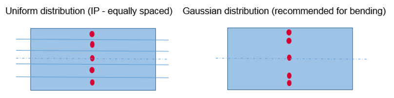
√ Uniformed or Gauss
√ Uniformed or Gauss
Anisotropic direction
√ √ √ + skew Anisotropic direction
√ √ √ Ply orientation change
√ Defined in /PROP/TYPE19
√ Defined in /PROP/TYPE19
√ Defined in /PLY
Angle between anisotropic axies
√ in /PROP/TYPE19
√ in /PROP/TYPE19
√ in /PLY
Layer/Ply thickness
√ Different in /PROP/TYPE19
√ Different in /PROP/TYPE19
√ Different in /PLY
Ipos + Layer/Ply position
√ √ √ Ipos=2,3,4 Layer/Ply offset
√ √ √ mat_IDi Material for each layer/ply
√ Must use same material type for all plies.
√ Different material type allows for each ply.
√ Different material type allows for each ply.
Commonly used Composite Material Law 25, 27, 36, 60, 72, 93 and user material 25, ≥28 and user material 25 and user material XFEM compatibility (crack propagation) √ With /FAIL/JOHNSON and /FAIL/TBUTCHER
Plyxfem Delamination between layer/ply
√ Minterply Material between layer/ply
√ Only with LAW1+/FAIL/LAD_DAM
Layer (Ply) Number N (Nply_IDi) and Integration Points each Layer (Ply)
For layer-based modeling which use /PROP/TYPE10, /TYPE11. N is the number of layers through the shell thickness. For these properties, there is one integration point (IP) each layer.
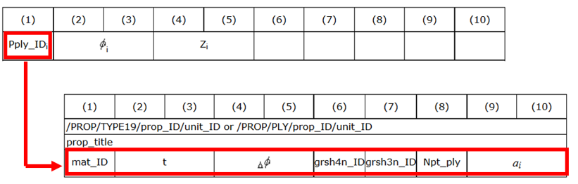
For ply-based modeling, which use /PROP/TYPE17, /TYPE51 or /STACK/PCOMPP. Pply_IDi is the number of plies through the shell thickness. Plies could be combined until n plies for these properties.
For TYPE17 only one integration point is allowed while for TYPE51 and /STACKF up to 9 integration points are allowed. The number of integration points are defined with option “Npt_ply” in property TYPE19 or /PLY.
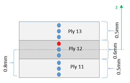
It is possible to print animation results (plastic strain, damage, stress and strain tensor) in each specific integration point with /ANIM/SHELL/IDPLY/Keyword4/I/J (or /ANIM/SHELL/Keyword3/N/NIP).
For instance, use /ANIM/SHELL/IDPLY/EPSP/2/3 (or /ANIM/SHELL/EPSP/2/3) to print plastic strain in third integration point (red highlighted integration point in Figure 6) of second ply (ply name Ply12). For additional print info about Integration points through shell thickness for composite properties, refer to Shell stress tensor output in animation. in the FAQs.
Anisotrophy in Layer (Ply)
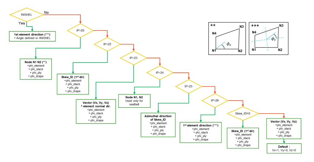
- The reference vector for the first anisotropic direction of the material may be
defined with the flag IP, local coordinate system skew_ID or vector (Vx, Vy,
Vz)
IP=0, skew_ID=0 Vector (Vx, Vy, Vz) IP=0, skew_ID≠0 First direction (local X) of the local coordinate system skew_ID. IP=20 node N1 and N2 of the shell elements 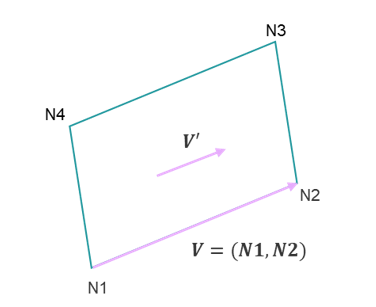
IP=22 First direction (local X) of the local coordinate system skew_ID. 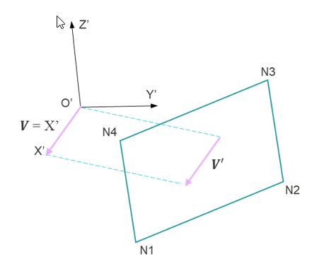
IP=23 Product of vector (Vx, Vy, Vz) and the shell element normal direction n 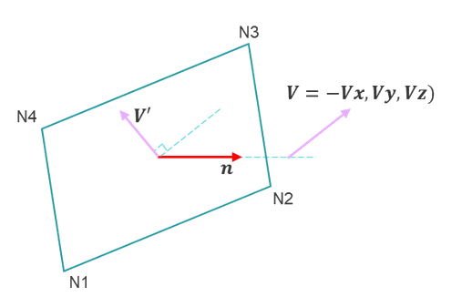
IP=24 (for seatbelt element only) Shell seatbelt (only for /MAT/LAW119) width direction from 1st direction of skew_ID or with the node N1 and N2 of the shell elements. skew_ID=0: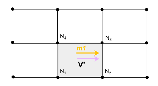
skew_ID≠0: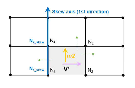
IP=25 Azimuthal direction defined with local cylindrical coordinate system skew_ID (2nd direction). 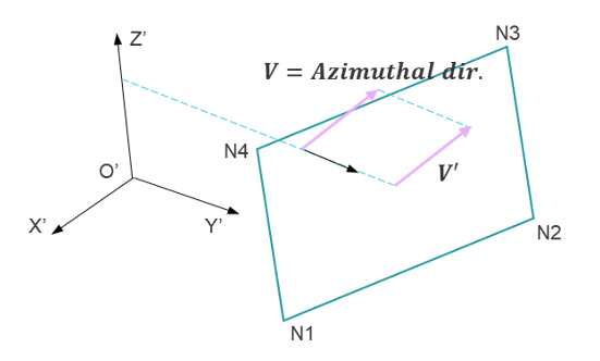
IP=26 First axis of the element coordinate system 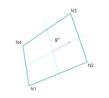
- The first material direction is defined from the reference vector and the
anisotropy angles defined as:Where,
- is defined per ply in stack
- is defined on the element
- is defined on the ply
- is defined in the drape table
*: only for /PROP/TYPE17, /PROP/TYPE51 and /STACK
- Drape tables (/DRAPE) can be defined for specific shell
elements or shell element groups with option drape_ID in
/PROP/TYPE19 and /PLY. With this
feature, the angle of anisotropic (orthotropic) direction may be changed with
and the thinning factor.
- Only 1 slice per ply is available in the stack /PROP/TYPE17
- Several slices per ply may be defined for the stack /STACK or /PROP/TYPE51 properties using plies with multiple integration points
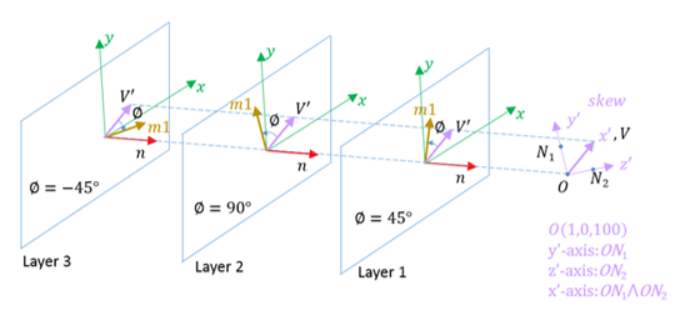
- A Composite material can be orthotropic or anisotropic. In Radioss it is possible to describe this characteristic
with anisotropic axis angle
in ply-based properties. In case of
, then it describes an orthotropic material. For
layer-based properties (TYPE10 and TYPE11) option
is not available, only orthotropic materials can
be defined.
Figure 9. 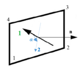
- The material direction will be overwritten by the direction defined in initial state file (/INISHE/ORTHO or /INISHE/ORTH_LOC).
Layer (Ply) Thickness and Position
- For /PROP/TYPE10, layer thickness is simply averaged by layer
numberand layers are automatically stacked one by one from bottom to top.
Figure 10. 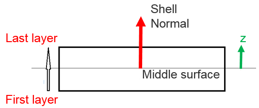
- For properties TYPE11, TYPE17, TYPE51 and /STACK, layer (ply)
position and thickness depend on option Ipos
- If Ipos=0
User layer (ply) thickness input will be taken, and layer (ply) position will be automatically calculated one by one from bottom to top; but if,
Then, layer (ply) thickness will be adjusted to , so that
Layer (ply) position will be then adjusted, as well.
- If Ipos=1
User layer(ply) input of thickness and position will be taken. Sum of layer thickness will not be checked against .
For more information, refer to Layer thickness and position calculation. in the FAQs.
- If Ipos=0
- For properties TYPE17, TYPE51 and /STACK, it is also possible
to offset the plies with Ipos=2, 3, 4
- Ipos=2: the shell element mid-surface is at
Z0 from the bottom of the ply
layout
Figure 11. 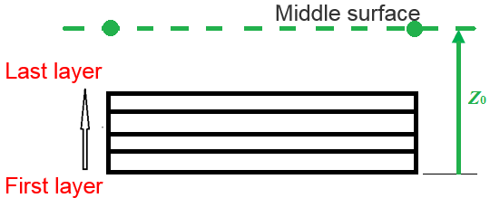
- Ipos=3: the top of the ply layout is coincident with the element
mid-surface
Figure 12. 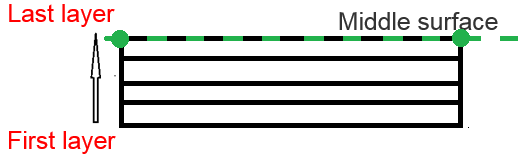
- Ipos=4: the bottom of the ply layout is coincident with the element
mid-surface
Figure 13. 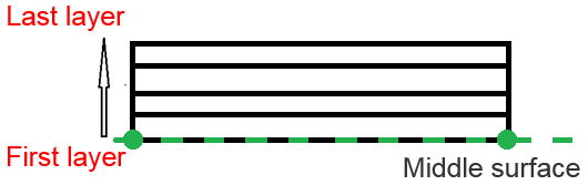
- Ipos=2: the shell element mid-surface is at
Z0 from the bottom of the ply
layout
- For properties /PROP/TYPE17, /PROP/TYPE51
and /STACK, ply thickness may be changed by option
in /DRAPE (defined in
/PROP/TYPE19 or /PLY). Then updated
ply thickness is:
Composite Material Used for Layer (Ply)
- Material for layer (ply)
- For property TYPE10, composite uses material defined in /PART
- For properties TYPE11 and TYPE17, composite uses material defined in option mat_IDi. Different material ID may be defined for each layer (ply). But they must use same material type. If LAW25 is used, then several different LAW25 cards may be used for different layers (plies).
- For properties TYPE51 and /STACK, composite also uses material defined in option mat_IDi and different material type or ID may be used for each ply.
- Material between pliesFor property TYPE17, it is possible to define delamination between plies or stacks (with Plyxfem=2). This is very useful for delamination is the main driven of composite failure. The material between plies defined with Minterply. For the moment, LAW1+/FAIL/LAD_DAM could be used to describe three different type of ply delamination.
Figure 14. 
And then in this case additional variable are added on each node of ply by computation to simulate the delamination failure between plies.Figure 15. 
Solid Element
New composite technology allows thicker part production, modeling those parts with shell elements may not be suitable. Thick shell modeling can solve this problem. Compared with shell elements, thick shells may directly connect with other solid parts
| /PROP/TYPE22 (TSH_COMP) | ||
|---|---|---|
| Layer Numbers | Isolid=14: Iint=9~200 |
Isolid=15: |
| IP of each layer/ply | Inpts=ijk=2~9 | Inpts=j=1~200 |
| Integration formulation | ||
| + , Anisotropic direction | √ | |
| + skew, Anisotropic direction | √ | |
| , Ply orientation change | ||
| , Angle between anisotropic axis | ||
| , Layer/Ply thickness | √ defined with factor |
|
| Ipos + , Layer/Ply position | √ | |
| Ipos=2,3,4, Layer/Ply offset | ||
| mat_IDi, Material for each layer/ply | √ Different material type allows for each layer. |
|
| Commonly used Composite Material LAW | LAW12, LAW14, LAW25 and user material | |
| Plyxfem, Delamination between layer/ply | ||
| Minterply, Material between layer/ply | ||
- Layer Number and Integration Points Each Layer
The layer number is defined using the option Iint. Iint is only used for Isolid=14 when the number of layers > 9.
In this case, the thickness direction integration point defined by Inpts should be zero.
Example, Icstr = 010; Inpts = 202; Iint = 100 for a number of 100 layers in "s" direction
- Anisotrophy in Layer (Ply)Similar to shell property /PROP/TYPE11, reference vector and angle are used to define the material direction 1. The reference vector project to the middle surface of solid element and turn degree is the material direction 1.
Figure 16. 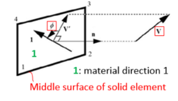
- Layer Thickness and Position
For solid element thickness and position defined by element mesh.
- Composite Material Used for Layer
- With option mat_IDi, it is possible to use different material type for each layer
- Composite material LAW12, LAW14 and LAW25 could be used with this property
- Failure model /FAIL/HASHIN, /FAIL/PUCK and /FAIL/LAD_DAMA with these composite material laws are also accounted for
- Material referred to in the corresponding /PART card is only used for time step and interface stiffness calculation
- For LAW25, it is assumed that (for solids and thick shells) the material is elastic in transverse direction (material direction 2 and 3) and the E33 value must be specified in such cases
For additional information, refer to Composite Material and Composite Failure Model.