Tracked Vehicle Modeling
In this tutorial, you will learn how to use MotionView to build a tracked vehicle and simulate a track vehicle on a soft soil road passing over a few obstacles.
Before you begin, copy the file(s) used in this tutorial to your
working directory.
Model Overview
-
From the File menu, click on Extension
Manager and load the Vehicle Tools
extension.
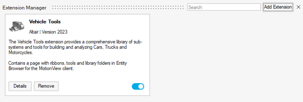
Figure 1. -
Review the model.
- The model is in the mm, Kg, N, sec unit system.
- The model has two systems: Body and Suspension.
- The Body system contains the Vehicle body (Frame) and Engine fixed to each other.
- The Suspension system has three trailing arms connected with a torsional spring damper.
- There are two unresolved motions used to drive the vehicle, Motion Left and Motion Right.
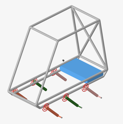
Figure 2.
Create Rolling Systems
-
From the Vehicle Tools menu, under Track
Builder select Rolling systems.
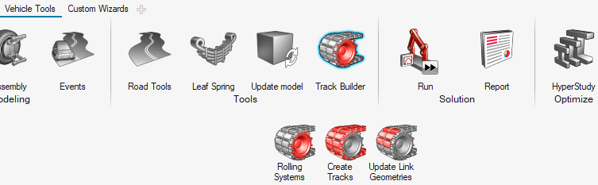
Figure 3.The Create rolling system dialog is shown below: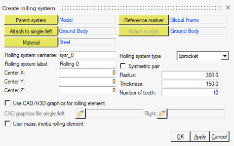
Figure 4. -
Click Apply to create the sprocket systems and continue
in the Creating rolling system dialog.
The complete dialog is displayed below:
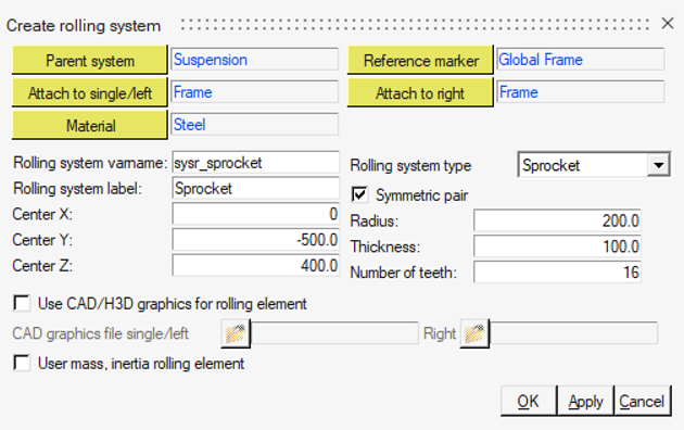
Figure 5. -
Repeat steps 2 to 9 using the following table to create three symmetric rolling
systems of type Wheel.
Tip: Use the Apply button to keep the dialog open when creating multiple rolling systems.
Parent System Attach to Single/Left Attach to Right Rolling system varname Rolling system label Center Radius Thickness X Y Z Suspension Front Arm-Left Front Arm-Right sysr_frontwheel Front Wheel 300 -500 0 200 100 Suspension Mid Arm-Left Mid Arm-Right sysr_midwheel Middle Wheel 800 -500 0 200 100 Suspension Rear Arm-Left Rear Arm-Right sysr_rearwheel Rear Wheel 1300 -500 0 200 100 The model with the rolling systems is shown below: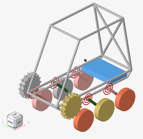
Figure 6. -
Update the joint of Motion Left to Sprocket
LH Joint Rev by selecting the revolute joint in the
Sprocket LH system.
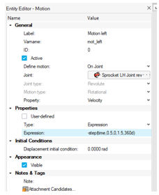
Figure 7.
Create Track Systems
-
From the Vehicle Tools menu, under Track
Builder select Create Tracks.
Figure 8.The Create track dialog is displayed: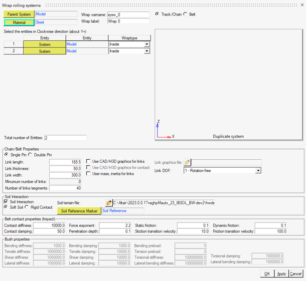
Figure 9. -
Select the Road Reference Marker as Soil
Reference Marker.
The complete dialog is displayed below:
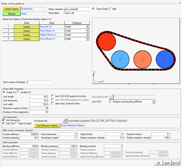
Figure 10. -
Click OK to create the left side track.
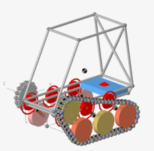
Figure 11. Left Side Track Created -
The completed model is shown below.
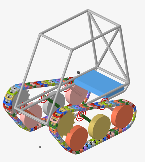
Figure 12. -
Click on Road Tools to invoke the dialog.
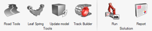
Figure 13. -
Under MDL, select a location to save the
heavy_clay_25_custom_obs.mdl file in the
<working directory>.
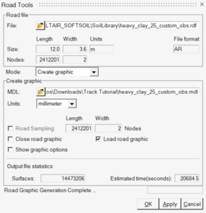
Figure 14. -
After road graphics creation, select the road graphics
in the Model Browser under the created Road Graphics systems
and define the Road Reference Marker in the Entity Editor.
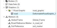
Figure 15.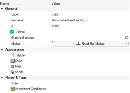
Figure 16. -
The Track with Terrain Graphics is shown below.
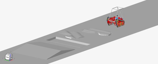
Figure 17.
Simulation and Post-Processing
-
Under the Vehicle Tools menu, go to Run and open the
Analysis settings dialog.
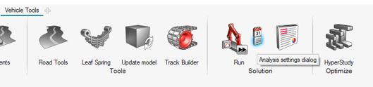
Figure 18. -
Select the Run Offline check box and click the
Run button.
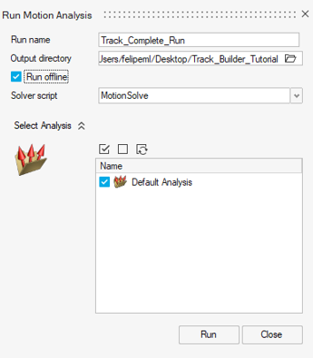
Figure 19. -
Click on the Open Model button, load the
Track_complete.h3d file in the panel, and click
Apply.
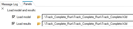
Figure 20. -
From the Animation toolbar, click the
 (Start/Pause Animation) button to animate the
model.
(Start/Pause Animation) button to animate the
model.
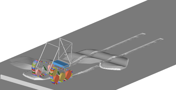
Figure 21. -
Click on the Contour option in the Ribbon to visualize
the soil plastic sinkage.
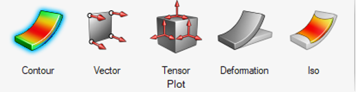
Figure 22. -
From the panel, select Plastic Sinkage as result type
and click Apply.
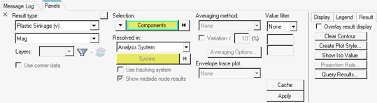
Figure 23.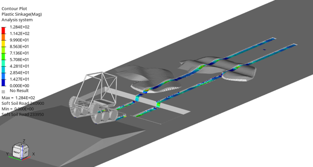
Figure 24. -
From the menu bar, select the HyperGraph
Line Chart application.
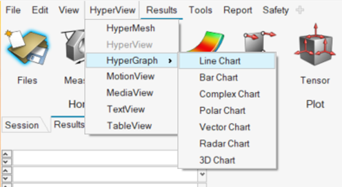
Figure 25. -
Under Y type select REQSUB, a list of soft soil results
is displayed. Select Track LH Link 0 and
RESULTS(2) to plot the sinkage of the left track link
0.
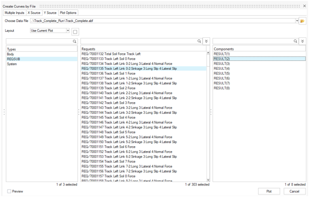
Figure 26.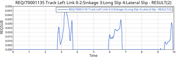
Figure 27.