ANSYS Interface
New Features
- Beam Meshing Tools
- Stiffener Mesh
- Mesh stiffeners are attached to shell elements. Support for Beam
(188&189) and Rod (Link180).
- Support mesh by proximity using free line but seeding nodes on the closest shells.
- Inherit orientation from the shell normal.
- Auto offset beams on top of the shell mesh.
- You can generate a stiffener on each edge of the source shell elements.
- The tool auto-generates the property SECTYPE and the associated
section (BEAM card) from the given beam section.
- You can leverage metadata beam section on parts holding free lines. These metadata are automatically created when importing Aveva Marine or OCX CAD formats.
- Mesh stiffeners are attached to shell elements. Support for Beam
(188&189) and Rod (Link180).
- Member Mesh
- Mesh lines/edges/node path with either Beam, Rod, or Pipe engineering configurations.
- Element type/section and property are created accordingly.
- Beam section types are filtered based on the desired configuration.
- for LINK180, the beam section area is directly mapped to
the to field area of the section entity.
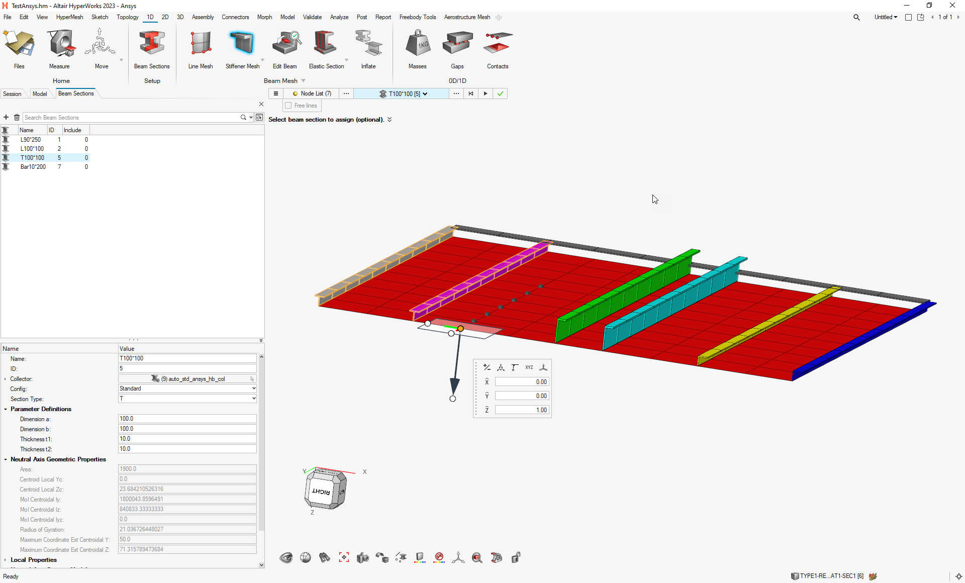
Figure 1.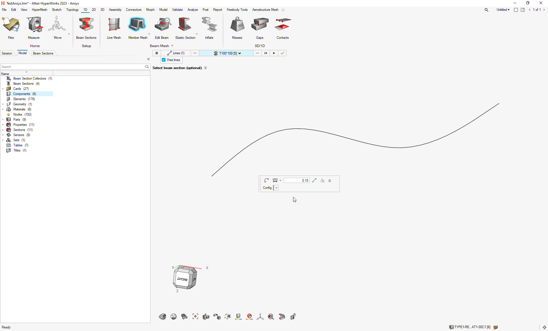
Figure 2.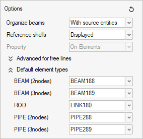
Figure 3.
- for LINK180, the beam section area is directly mapped to
the to field area of the section entity.
- Beam Edit Tools
- The Align tool is used to adjust elements' n1→n2 order.
- Reorder nodes so the X-axis follows the closest global or local system axis in ascending order.
- The tool supports all types of beam elements.
- Offset
- Offset beams on the shell mesh.
- Assign offset keys: CENTROID/SHEAR CENTER/ORIGIN.
- Apply the same offset as a reference element.
- Apply incremental offset with a manipulator or set directly
offset components.
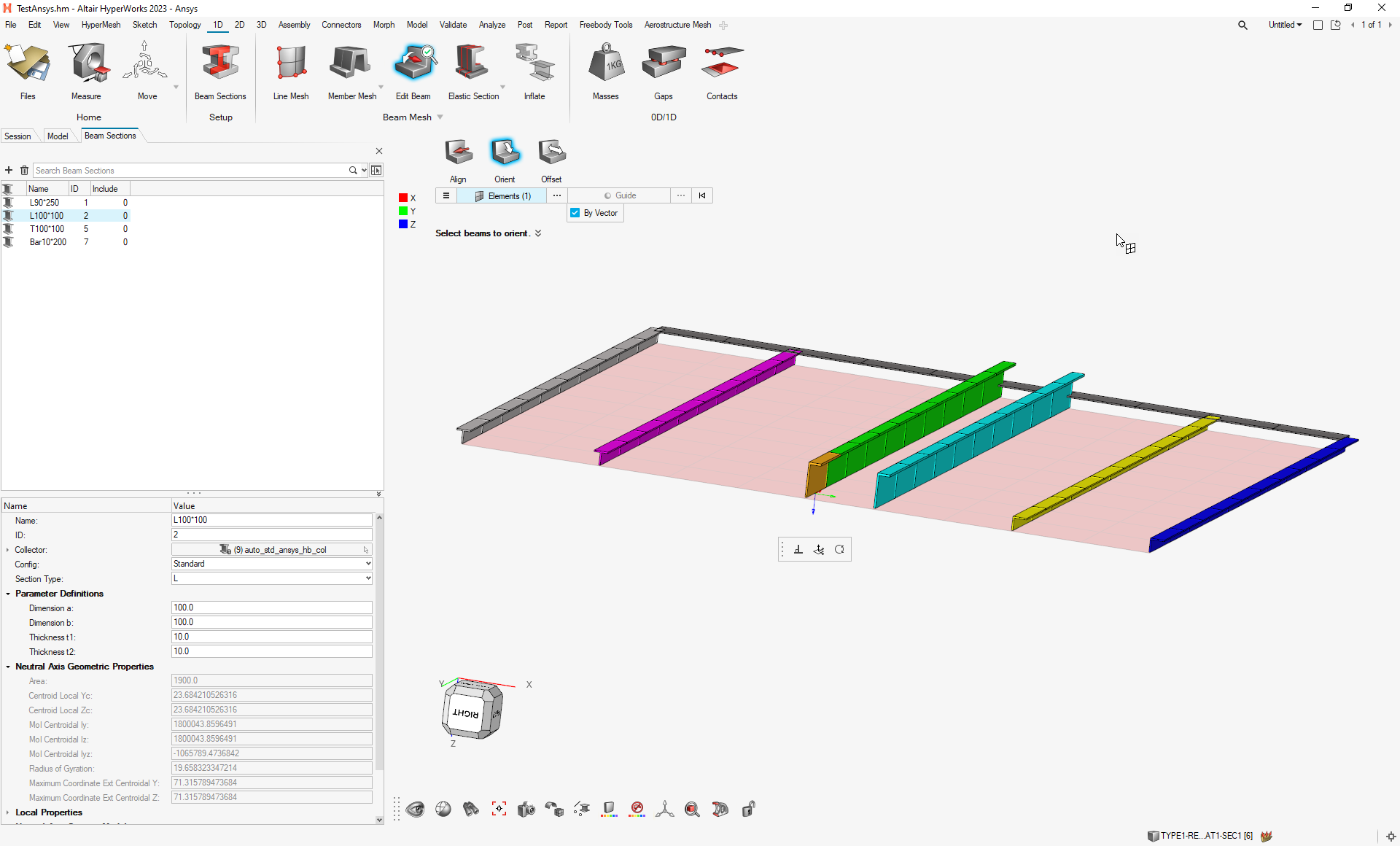
Figure 4.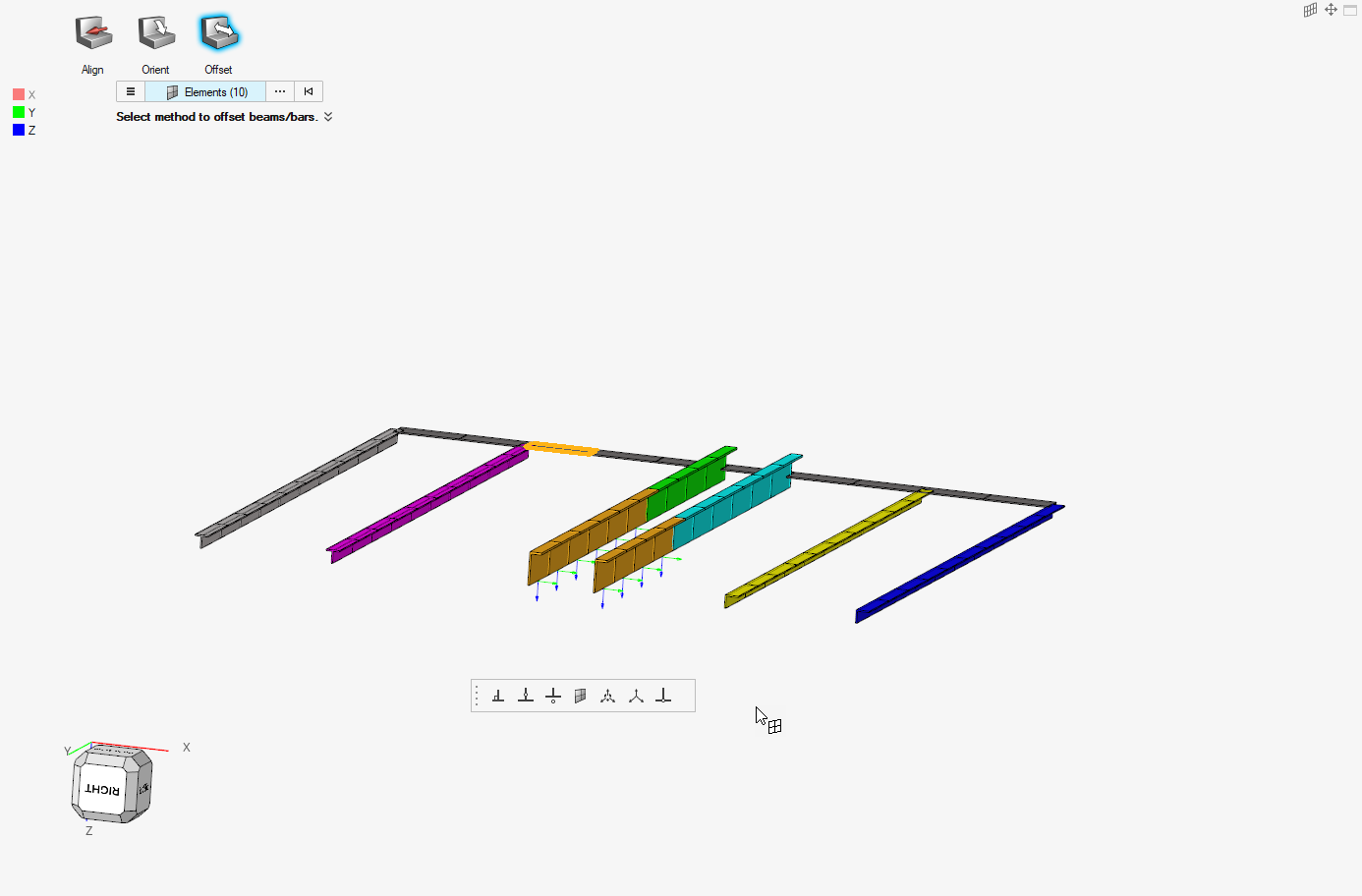
Figure 5.
- Inflate
- Convert Beams to Surface and Shell Mesh
- Beam188 with either standard beam section or shell beam section.
- The tool creates surfaces from the beam section midline.
- Generate 2D mesh (SHELL181) with thickness assigned.
- Convert Beams to Solids
- Beam188 with a standard beam section only.
- Generate solid geometry from beams.
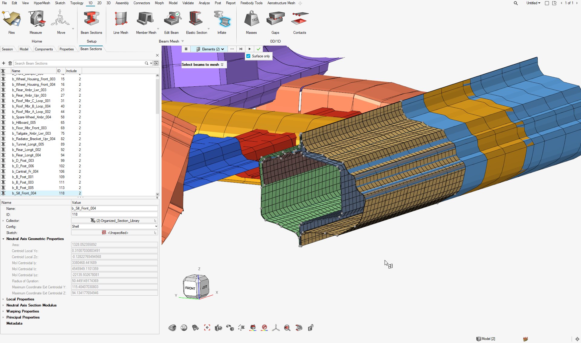
Figure 6.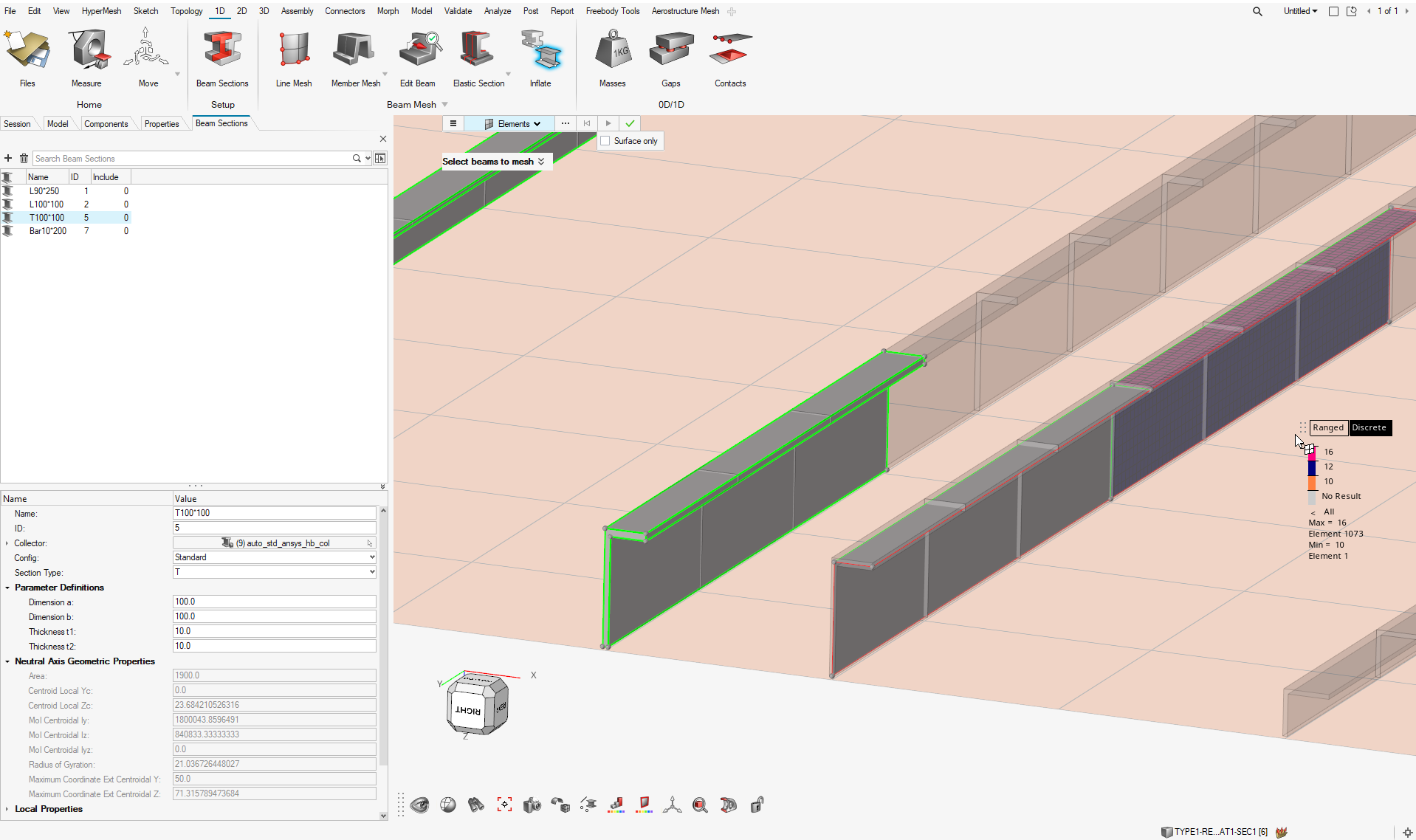
Figure 7.
Enhancements
- Mapping real constants of the COMBIN39p property to a curve entity has been added.