Vector Tool
Define an orientation using the Vector tool in the following ways:
-
Click and drag to move the base handle – the point in space where the
plane/vector is located. Then, drag the handle at the tip of the arrow to define
a vector, or drag two handles on the edges of the plane to define a plane.
Virtual Wind Tunnel for ultraFluidX takes advantage of the following principle: a plane can be defined with a vector (the plane is normal to the vector specified), just as a vector can be defined with a plane (the vector is normal to the plane specified).
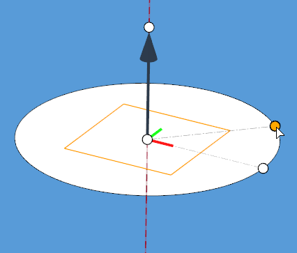
Figure 1. . Example defining a vector using the plane handles. A spin axis is defined normal to 3 locations on a circle.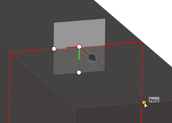
Figure 2. . Example defining a plane using the vector handles. A split plane is defined normal to a point and its perpendicular projection to an edge. -
Use the options in the microdialog to help position the
vector or plane.
 ,
,  ,
, 
- Align to one of the global axes, or type any vector components.

- Translate or rotate the Vector tool with precision.

- Edit handle coordinates.

- Reverse the direction of the vector.

- Align the vector/plane as normal or parallel to the current view.

- Select a Vector entity to align to, or assign a local coordinate System. After a new system is assigned, the Vector tool automatically repositions to its origin.
Tip: When a local system is assigned to the Vector tool, the system button is shown with a tick mark , indicating that the manipulator is now in
local system mode. Click this button again to change the assigned system
or reset it to go back to global system mode.
, indicating that the manipulator is now in
local system mode. Click this button again to change the assigned system
or reset it to go back to global system mode.