
UserDefinedComponents
User Defined Components
![]()
Library
Modelica/Mechanics/Translational/UsersGuide
Description
In this section some hints are given to define your own1-dimensional translational components which are compatible with theelements of this package.It is convenient to define a newcomponent by inheritance from one of the following base classes,which are defined in sublibraryInterfaces:
| Name | Description |
|---|---|
| PartialCompliant | Compliant connection of two translational 1-dim. flanges (used for force laws such as a spring or a damper). |
| PartialCompliantWithRelativeStates | Same as "PartialCompliant", but relative position and relative speed are defined as preferred states. Use this partial model if the force law needs anyway the relative speed. The advantage is that it is usually better to use relative positions between drive train components as states, especially, if the position is not limited. |
| PartialElementaryTwoFlangesAndSupport2 | Partial model for a 1-dim. translational component consisting of the flange of an input shaft, the flange of an output shaft and the support. |
| PartialForce | Partial model of an external force acting at the flange (accelerates the flange). |
| PartialTwoFlanges | General connection of two translational 1-dim. flanges. |
| PartialAbsoluteSensor | Measure absolute flange variables. |
| PartialRelativeSensor | Measure relative flange variables. |
The difference between these base classes are the auxiliaryvariables defined in the model and the relations betweenthe flange variables already defined in the base class.For example, in model PartialCompliant there is nosupport flange, whereas in modelPartialElementaryTwoFlangesAndSupport2there is a support flange.
The equations of a mechanical component are vector equations, i.e.,they need to be expressed in a common coordinate system.Therefore, a local axis of movement has to bedefined for a component. All vector quantities, such as cut-forces orvelocities have to be expressed according to this definition.Examples for such a definition are given in the following figurefor a mass component:
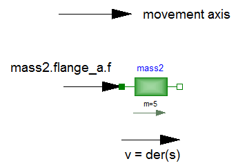
As can be seen, all vectors are directed into the directionof the movement axis. The positions in the flanges are definedcorrespondingly.
On first view, one may assume that the selected localcoordinate system has an influence on the usage of thecomponent. But this is not the case, as shown in the next figure:
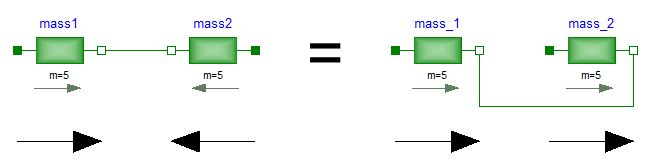
In the figure, the local axes of translation of the componentsare shown. The connection of two masses in the left and in theright part of the figure are completely equivalent, i.e., the rightpart is just a different drawing of the left part. This is due to thefact, that by a connection, the two local coordinate systems aremade identical and the (automatically) generated connection equations(= positions are identical, cut-forces sum-up to zero) are alsoexpressed in this common coordinate system. Therefore, even if inthe left figure it seems to be that the velocity vector ofmass2 goes from right to left, in reality it goes fromleft to right as shown in the right part of the figure, where thelocal coordinate systems are drawn such that they are aligned.Note, that the simple rule stated in sectionSign conventionsalso determines thatthe velocity of mass2 in the left part of thefigure is directed from left to right.
To summarize, the local coordinate system selected for a componentis just necessary in order that the equations of this componentare expressed correctly. The selection of the coordinate systemis arbitrary and has no influence on the usage of the component.Especially, the actual direction of, e.g., a cut-force is mosteasily determined by the rule of sectionSign conventions.A more strict determinationby aligning coordinate systems and then using the vector directionof the local coordinate systems, often requires a re-drawing of thediagram and is therefore less convenient to use.