Overview
Overview
![]()
Library
Modelica/Mechanics/Translational/UsersGuide
Description
This package contains components to model 1-dimensional translationalmechanical systems, including different types of masses,external forces, spring/damper elements,frictional elements, elastogaps, elements to measure position, velocity,acceleration or the cut-force of a flange. In sublibraryExamplesseveral examples are present to demonstrate the usage ofthe elements. Just open the corresponding example model and simulatethe model according to the provided description.
A unique feature of this library is the component-orientedmodeling of Coulomb friction elements, such as support friction.Even (dynamically) coupled friction elements can be handledwithout introducing stiffness, which leads to fast simulations.The underlying theory is based on the solution of mixedcontinuous/discrete systems of equations, i.e., equations where theunknowns are of type Real, Integer or Boolean.Provided appropriate numerical algorithms for the solution of such types ofsystems are available in the simulation tool, the simulation of(dynamically) coupled friction elements of this library isefficient and reliable.
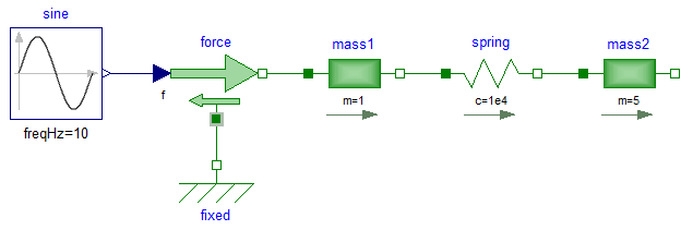
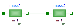
A simple example of the usage of this library is given in thefigure above. This model consists of a mass1 with mass m = 1 kg whichis connected via a spring to a mass2 with mass m = 5 kg.The left mass is driven via an external, sinusoidal force.The filled and non-filled green squares at the left andright side of a component represent mechanical flanges.Drawing a line between such squares means that the correspondingflanges are rigidly attached to each other.By convention in this library, the connector characterized as afilled green square is called flange_a and placed at theleft side of the component in the "design view" and the connectorcharacterized as a non-filled green square is called flange_band placed at the right side of the component in the "design view".The two connectors are completely identical, with the onlyexception that the graphical layout is a little bit different in orderto distinguish them for easier access of the connector variables.For example, mass1.flange_a.f is the cut-force in the connectorflange_a of component mass1.
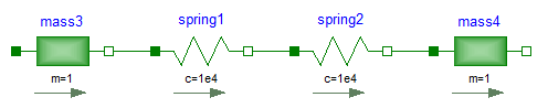
The components of thislibrary can be connected together in an arbitrary way. E.g., it ispossible to connect two springs or two shafts with mass directlytogether, see figure below.