
SignConventions
Sign Conventions
![]()
Library
Modelica/Mechanics/Rotational/UsersGuide
Description
The variables of a component of this library can be accessed in theusual way. However, since most of these variables are basically elementsof vectors, i.e., have a direction, the question arises how thesigns of variables shall be interpreted. The basic idea is explainedat hand of the following figure:
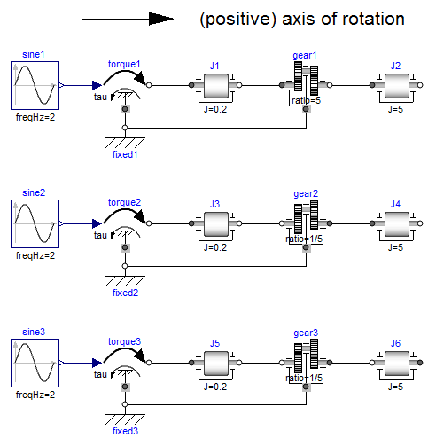
In the figure, three identical drive trains are shown. The onlydifference is that the gear of the middle drive train and thegear as well as the right inertia of the lower drive trainare horizontally flipped with regards to the upper drive train.The signs of variables are now interpreted in the following way:Due to the 1-dimensional nature of the model, all components arebasically connected together along one line (more complicatedcases are discussed below). First, one has to definea positive direction of this line, called axis of rotation.In the top of the figure this is characterized by an arrowand a corresponding text. The simple rule is now:If a variable of a component is positive and can be interpreted asthe element of a vector (e.g., torque or angular velocity vector), thecorresponding vector is directed into the positive directionof the axis of rotation. In the following figure, the right-mostinertias of the figure above are displayed with the positivevector direction displayed according to this rule:
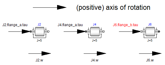
The cut-torques J2.flange_a.tau, J4.flange_a.tau and J6.flange_b.tauof the right inertias are all identical and are directed into thedirection of rotation if the values are positive. Similarly,the angular velocities J2.w, J4.w and J6.w of the right inertiasare all identical and are also directed into thedirection of rotation if the values are positive. Some specialcases are shown in the next figure:
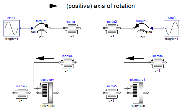
In the upper part of the figure, two variants of the connection of anexternal torque and an inertia are shown. In both cases, a positivesignal input into the torque component accelerates the inertiasinertia1 and inertia2 into the positive axis of rotation,i.e., the angular accelerations inertia1.a and inertia2.aare positive and are directed along the "axis of rotation" arrow.In the lower part of the figure the connection of inertias witha planetary gear is shown. Note, that the three flanges of theplanetary gearbox are located along the axis of rotation and thatthe axis direction determines the positive rotation along theseflanges. As a result, the positive rotation for inertia4 and inertia6is as indicated with the additional black arrows.