
Brake
Brake based on Coulomb friction
![]()
Library
Modelica/Mechanics/Rotational/Components
Description
This component models a brake, i.e., a component where a frictionaltorque is acting between the housing and a flange and a controlled normalforce presses the flange to the housing in order to increase friction.The normal force fn has to be provided as input signal f_normalized in a normalized form(0 ≤ f_normalized ≤ 1),fn = fn_max*f_normalized, where fn_max has to be provided as parameter.Friction in the brake is modelled in the following way:
When the absolute angular velocity "w" is not zero, the friction torqueis a function of the velocity dependent friction coefficient mu(w), ofthe normal force "fn", and of a geometry constant "cgeo" which takes intoaccount the geometry of the device and the assumptions on the frictiondistributions:
frictional_torque = cgeo * mu(w) * fn
Typical values of coefficients of friction mu:
- 0.2 … 0.4 for dry operation,
- 0.05 … 0.1 when operating in oil.
When plates are pressed together, where ri is the inner radius, ro is the outer radius and N is the number of friction interfaces, the geometry constant is calculated in the following way under the assumption of a uniform rate of wear at the interfaces:
cgeo = N*(r0 + ri)/2
The positive part of the friction characteristic mu(w), w >= 0, is defined via table mu_pos (first column = w, second column = mu). Currently, only linear interpolation in the table is supported.
When the absolute angular velocity becomes zero, the elements connected by the friction element become stuck, i.e., the absolute angle remains constant. In this phase the friction torque is calculated from a torque balance due to the requirement, that the absolute acceleration shall be zero. The elements begin to slide when the friction torque exceeds a threshold value, called the maximum static friction torque, computed via:
frictional_torque = peak * cgeo * mu(w=0) * fn (peak >= 1)
This procedure is implemented in a "clean" way by state events andleads to continuous/discrete systems of equations if friction elementsare dynamically coupled. The method is described in(see also a short sketch in UsersGuide.ModelingOfFriction):
- Otter M., Elmqvist H., and Mattsson S.E. (1999):
- Hybrid Modeling in Modelica based on the Synchronous Data Flow Principle. CACSD'99, Aug. 22.-26, Hawaii.
More precise friction models take into account the elasticity of thematerial when the two elements are "stuck", as well as other effects,like hysteresis. This has the advantage that the friction element canbe completely described by a differential equation without events. Thedrawback is that the system becomes stiff (about 10-20 times slowersimulation) and that more material constants have to be supplied whichrequires more sophisticated identification. For more details, see thefollowing references, especially (Armstrong and Canudas de Wit 1996):
- Armstrong B. (1991):
- Control of Machines with Friction. Kluwer Academic Press, Boston MA.
- Armstrong B., and Canudas de Wit C. (1996):
- Friction Modeling and Compensation. The Control Handbook, edited by W.S.Levine, CRC Press, pp. 1369-1382.
- Canudas de Wit C., Olsson H., Åström K.J., and Lischinsky P. (1995):
- A new model for control of systems with friction. IEEE Transactions on Automatic Control, Vol. 40, No. 3, pp. 419-425.
See also the discussionState Selectionin the User's Guide of the Rotational library.
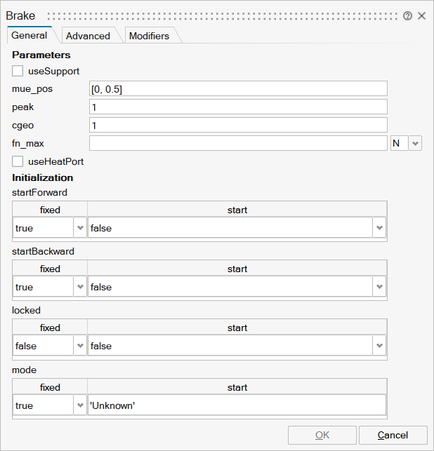
Parameters
| Name | Label | Description | Data Type | Valid Values |
|---|---|---|---|---|
mo_useSupport | useSupport | = true, if support flange enabled, otherwise implicitly grounded | Number | 0 |
mo_mu_pos | mu_pos | Positive sliding friction coefficient [-] as function of w_rel [rad/s] (w_rel>=0) | Matrix of size Mx2 | |
mo_peak | peak | Peak for maximum value of mu at w==0 (mu0_max = peak*mu_pos[1,2]) | Scalar | |
mo_cgeo | cgeo | Geometry constant containing friction distribution assumption | Scalar | |
mo_fn_max | fn_max | Maximum normal force | Scalar | |
mo_useHeatPort | useHeatPort | = true, if heatPort is enabled | Number | 0 |
mo_startForward | startForward | startForward | Structure | |
mo_startForward/fixed | fixed | Cell of scalars | true | |
mo_startForward/start | start | Cell of scalars | true | |
mo_startBackward | startBackward | startBackward | Structure | |
mo_startBackward/fixed | fixed | Cell of scalars | true | |
mo_startBackward/start | start | Cell of scalars | true | |
mo_locked | locked | locked | Structure | |
mo_locked/fixed | fixed | Cell of scalars | true | |
mo_locked/start | start | Cell of scalars | true | |
mo_mode | mode | mode | Structure | |
mo_mode/fixed | fixed | Cell of scalars | true | |
mo_mode/start | start | Cell of scalars |
| Name | Label | Description | Data Type | Valid Values |
|---|---|---|---|---|
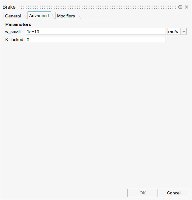
mo_w_small | w_small | Relative angular velocity near to zero if jumps due to a reinit(..) of the velocity can occur (set to low value only if such impulses can occur) | Scalar | |
mo_K_locked | K_locked | Gain driving the relative motion between the friction elements to 0 when locked. This parameter should only be non-zero when using the model with fixed-step integration | Scalar |
| Name | Label | Description | Data Type | Valid Values |
|---|---|---|---|---|
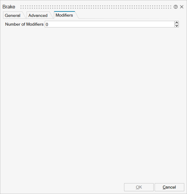
mo__nmodifiers | Number of Modifiers | Specifies the number of modifiers | Number | |
mo__modifiers | Modifiers | Add new modifier | Structure | |
mo__modifiers/varname | Variable name | Cell of strings | 'phi_support' | |
mo__modifiers/attribute | Attribute | Cell of strings | 'start' | |
mo__modifiers/value | Value |
Ports
| Name | Type | Description | IO Type | Number |
|---|---|---|---|---|
flange_a | implicit | Flange of left shaft | input | 1 |
flange_b | implicit | Flange of right shaft | output | 1 |
f_normalized | implicit | Normalized force signal 0..1 (normal force = fn_max*f_normalized; brake is active if > 0) | input | 2 |
Port 4 | implicit | Support/housing of component | input | mo_useSupport |
Port 5 | implicit | Optional port to which dissipated losses are transported in form of heat | input | mo_useHeatPort |