
FirstExample
A first example
![]()
Library
Modelica/Mechanics/MultiBody/UsersGuide/Tutorial
Description
As a first example it shall be demonstrated how to build up, simulateand animate a simple pendulum.
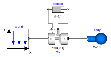
A simple pendulum consisting of a body and a revolute jointwith linear damping in the joint, is first build-up asModelica composition diagram, resulting in:
In the following figure the location of the usedmodel components is shown. Drag these components in the diagram layerand connect them according to the figure:
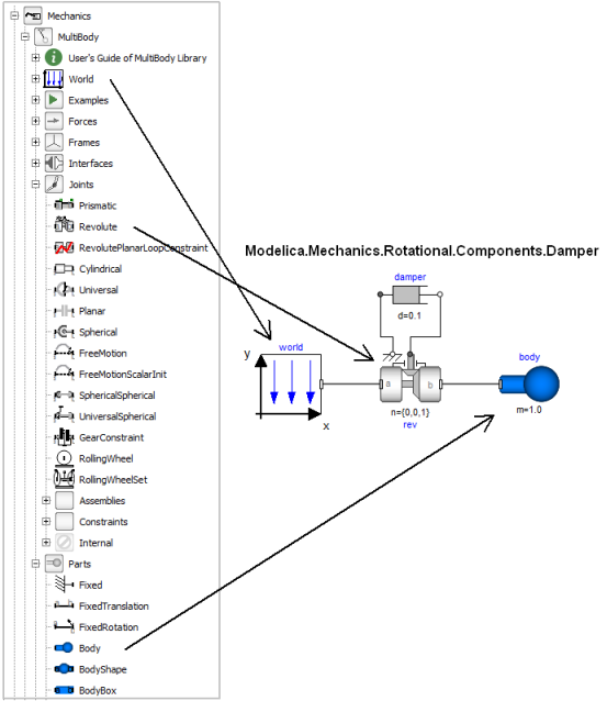
Every model that uses model components from the MultiBody librarymust have an instance of the Modelica.Mechanics.MultiBody.World model on highest level.The reason is that in the world object the gravity field is defined(uniform gravity or point gravity), as well as the default sizes ofanimation shapes and this information is reported to all usedcomponents. If the World object is missing, a warning message isprinted and an instance of the World object with default settings isautomatically utilized (this feature is defined with annotations).
In a second step the parameters of the dragged components need to bedefined. Some parameters are vectors that have to be defined with respectto a local coordinate system of the corresponding component. The easiestway to perform this is to define a reference configuration of yourmulti-body model: In this configuration, the relative coordinates ofall joints are zero. This means that all coordinate systems on allcomponents are parallel to each other. Therefore, this just meansthat all vectors are resolved in the world frame in this configuration.
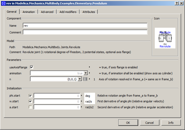
The reference configuration for the simple pendulum shall be definedin the following way: The y-axis of the world frame is directedupwards, i.e., the opposite direction of the gravity acceleration.The x-axis of the world frame is orthogonal to it. The revolute jointis placed in the origin of the world frame. The rotation axis of the revolutejoint is directed along the z-axis of the world frame. The body isplaced on the x-axis of the world frame (i.e., the rotation angle of therevolute joint is zero, when the body is on the x-axis).In the following figures the definition of this reference configurationis shown in the parameter menus of the revolute joint and the body:
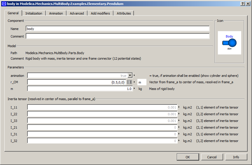
Translate and simulate the model.Automatically, all defined components are visualized inan animation using default absolute or relative sizesof the components. For example, a body is visualized asa sphere and as a cylinder. The default size of the sphere is definedas parameter in the world object. You may change this sizein the "Animation" parameter menu of the body (see parameter menuabove). The default size of the cylinder is defined relativelyto the size of the sphere (half of the sphere size).With default settings, the following animation is defined:
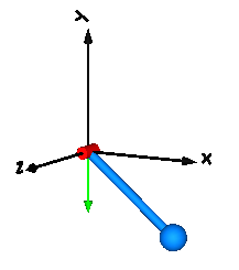
The world coordinate system is visualized as coordinate systemwith axes labels. The direction of the gravity accelerationvector is shown as green arrow. The red cylinder representsthe rotation axis of the revolute joint and the light blueshapes represent the body. The center of mass of the body isin the middle of the light blue sphere.