RevoluteWithLengthConstraint
Revolute joint where the rotation angle is computed from a length constraint (1 degree-of-freedom, no potential state)
![]()
Library
Modelica/Mechanics/MultiBody/Joints/Internal
Description
Joint where frame_b rotates around axis n which is fixed in frame_a.The two frames coincide when "phi + phi_offset = 0", where"phi_offset" is a parameter with a zero defaultand "phi" is the rotation angle.
This variant of the revolute joint is designed to work togetherwith a length constraint in a kinematic loop. This means that theangle of the revolute joint, phi, is computed such that thelength constraint is fulfilled.
Usually, this joint should not be used by a user of the MultiBodylibrary. It is only provided to built-up the Modelica.Mechanics.MultiBody.Joints.Assemblies.JointXYZjoints.
In releases before version 3.0 of the Modelica Standard Library, it was possibleto activate the torque projection equation (= cut-torque projected to the rotationaxis must be identical to the drive torque of flange axis) via parameteraxisTorqueBalance. This is no longer possible, since otherwise thismodel would not be "balanced" (= same number of unknowns as equations).Instead, when using this model in version 3.0 and later versions,the force in the length constraint component (Joints.SphericalSpherical orJoints.UniversalSpherical) must be calculated such that the driving torquein direction of the rotationaxis is (RC shall be the name of the instance of RevoluteWithLengthConstraint):
0 = RC.axis.tau + RC.e*RC.frame_b.t;
If this equation is used, usually the force in the length constraintand the second derivative of the revolute angle will be part of a linearalgebraic system of equations. In some cases it is possible to solvethis system of equations locally, i.e., provide the rod force directlyas function of the revolute constraint torque. In any case, this projectionequation or an equivalent one has to be provided via variable "constraintResidue" in the "Advanced"menu of "Joints.SphericalSpherical" or "Joints.UniversalSpherical".
Parameters

| Name | Label | Description | Data Type | Valid Values |
|---|---|---|---|---|
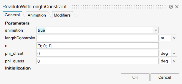
mo_animation | animation | = true, if animation shall be enabled | Scalar | true |
mo_lengthConstraint | lengthConstraint | Fixed length of length constraint | Scalar | |
mo_n | n | Axis of rotation resolved in frame_a (= same as in frame_b) | Vector of size 3 | |
mo_phi_offset | phi_offset | Relative angle offset (angle = phi + from_deg(phi_offset)) | Scalar | |
mo_phi_guess | phi_guess | Select the configuration such that at initial time |phi - from_deg(phi_guess)| is minimal | Scalar | |
mo_positiveBranch | positiveBranch | Based on phi_guess, selection of one of the two solutions of the non-linear constraint equation | Scalar | true |
mo_e | e | Unit vector in direction of rotation axis, resolved in frame_a | Vector of size 3 | |
mo_k1a | k1a | k1a | Structure | |
mo_k1a/fixed | fixed | Cell of scalars | true | |
mo_k1a/start | start | Cell of scalars |

| Name | Label | Description | Data Type | Valid Values |
|---|---|---|---|---|
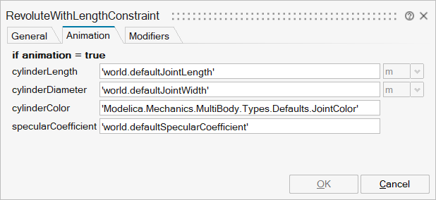
mo_cylinderLength | cylinderLength | Length of cylinder representing the joint axis | Scalar | |
mo_cylinderDiameter | cylinderDiameter | Diameter of cylinder representing the joint axis | Scalar | |
mo_cylinderColor | cylinderColor | Color of cylinder representing the joint axis | Vector of size 3 | |
mo_specularCoefficient | specularCoefficient | Reflection of ambient light (= 0: light is completely absorbed) | Scalar |

| Name | Label | Description | Data Type | Valid Values |
|---|---|---|---|---|
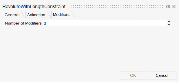
mo__nmodifiers | Number of Modifiers | Specifies the number of modifiers | Number | |
mo__modifiers | Modifiers | Add new modifier | Structure | |
mo__modifiers/varname | Variable name | Cell of strings | 'phi' | |
mo__modifiers/attribute | Attribute | Cell of strings | 'start' | |
mo__modifiers/value | Value |
Ports
| Name | Type | Description | IO Type | Number |
|---|---|---|---|---|
frame_a | implicit | Coordinate system a fixed to the component with one cut-force and cut-torque | input | 1 |
frame_b | implicit | Coordinate system b fixed to the component with one cut-force and cut-torque | output | 1 |
axis | implicit | 1-dim. rotational flange that drives the joint | input | 2 |
bearing | implicit | 1-dim. rotational flange of the drive bearing | output | 2 |
position_a | implicit | Position vector from frame_a to frame_a side of length constraint, resolved in frame_a of revolute joint | input | 3 |
position_b | implicit | Position vector from frame_b to frame_b side of length constraint, resolved in frame_b of revolute joint | input | 4 |