
Introduction
Introduction to phasors
![]()
Library
Modelica/Electrical/QuasiStationary/UsersGuide/Overview
Description
The purely sinusoidal voltage

in the time domain can be represented by a complexrms phasor
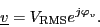
For these quasi stationaryphasor the following relationship applies:
This equation is also illustrated in Fig. 1.
 |
From the above equation it is obvious that for t = 0the time domain voltage is v = cos(φv).The complex representation of the phasor corresponds with this instance, too, sincethe phasor is leading the real axis by the angle φv.
The explanation given for sinusoidal voltages can certainly also be appliedto sinusoidal currents.