
AIM_SlipRing
Asynchronous induction machine with slipring rotor
![]()
Library
Modelica/Electrical/Machines/BasicMachines/AsynchronousInductionMachines
Description
Model of a three phase asynchronous induction machine with slipring rotor.
Resistance and stray inductance of stator and rotor are modeled directly in stator respectively rotor phases, then using space phasor transformation and a stator-fixed AirGap model. The machine models take the following loss effects into account:
- heat losses in the temperature dependent stator winding resistances
- heat losses in the temperature dependent rotor winding resistances
- friction losses
- core losses (only eddy current losses, no hysteresis losses)
- stray load losses
Default values for machine's parameters (a realistic example) are:
| number of pole pairs p | 2 | |
| stator's moment of inertia | 0.29 | kg.m2 |
| rotor's moment of inertia | 0.29 | kg.m2 |
| nominal frequency fNominal | 50 | Hz |
| nominal voltage per phase | 100 | V RMS |
| nominal current per phase | 100 | A RMS |
| nominal torque | 161.4 | Nm |
| nominal speed | 1440.45 | rpm |
| nominal mechanical output | 24.346 | kW |
| efficiency | 92.7 | % |
| power factor | 0.875 | |
| stator resistance | 0.03 | Ohm per phase at reference temperature |
| reference temperature TsRef | 20 | °C |
| temperature coefficient alpha20s | 0 | 1/K |
| rotor resistance | 0.04 | Ohm per phase at reference temperature |
| reference temperature TrRef | 20 | °C |
| temperature coefficient alpha20r | 0 | 1/K |
| stator reactance Xs | 3 | Ohm per phase |
| rotor reactance Xr | 3 | Ohm per phase |
| total stray coefficient sigma | 0.0667 | |
| turnsRatio | 1 | effective ratio of stator and rotor current |
| stator operational temperature TsOperational | 20 | °C |
| rotor operational temperature TrOperational | 20 | °C |
| These values give the following inductances: | ||
| stator stray inductance per phase | Xs * (1 - sqrt(1-sigma))/(2*pi*fNominal) | |
| rotor stray inductance | Xr * (1 - sqrt(1-sigma))/(2*pi*fNominal) | |
| main field inductance per phase | sqrt(Xs*Xr * (1-sigma))/(2*pi*f) |
Parameter turnsRatio could be obtained from the following relationshipat standstill with open rotor circuit at nominal voltage and nominal frequency,
using the locked-rotor voltage VR, no-load stator current I0 and powerfactor PF0:
turnsRatio * VR = Vs - (Rs + j Xs,sigma) I0
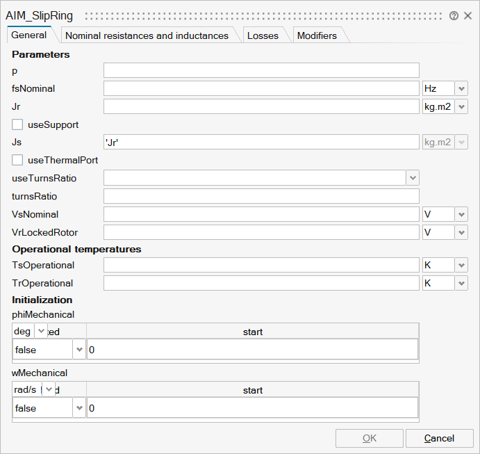
Parameters
| Name | Label | Description | Data Type | Valid Values |
|---|---|---|---|---|
mo_m | m | Number of phases | Scalar | |
mo_p | p | Number of pole pairs (Integer) | Scalar | |
mo_fsNominal | fsNominal | Nominal frequency | Scalar | |
mo_Jr | Jr | Rotor's moment of inertia | Scalar | |
mo_useSupport | useSupport | Enable / disable (=fixed stator) support | Number | 0 |
mo_Js | Js | Stator's moment of inertia | Scalar | |
mo_useThermalPort | useThermalPort | Enable / disable (=fixed temperatures) thermal port | Number | 0 |
mo_useTurnsRatio | useTurnsRatio | Use turnsRatio or calculate from locked-rotor voltage? | Scalar | true |
mo_turnsRatio | turnsRatio | Effective number of stator turns / effective number of rotor turns | Scalar | |
mo_VsNominal | VsNominal | Nominal stator voltage per phase | Scalar | |
mo_VrLockedRotor | VrLockedRotor | Locked-rotor voltage per phase | Scalar | |
mo_internalTurnsRatio | internalTurnsRatio | Scalar | ||
mo_TsOperational | TsOperational | Operational temperature of stator resistance | Scalar | |
mo_TrOperational | TrOperational | Operational temperature of rotor resistance | Scalar | |
mo_phiMechanical | phiMechanical | phiMechanical | Structure | |
mo_phiMechanical/fixed | fixed | Cell of scalars | true | |
mo_phiMechanical/start | start | Cell of scalars | ||
mo_wMechanical | wMechanical | wMechanical | Structure | |
mo_wMechanical/fixed | fixed | Cell of scalars | true | |
mo_wMechanical/start | start | Cell of scalars |
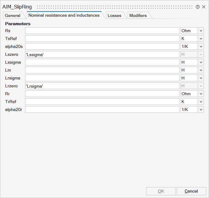
| Name | Label | Description | Data Type | Valid Values |
|---|---|---|---|---|
mo_Rs | Rs | Stator resistance per phase at TRef | Scalar | |
mo_TsRef | TsRef | Reference temperature of stator resistance | Scalar | |
mo_alpha20s | alpha20s | Temperature coefficient of stator resistance at 20 degC | Scalar | |
mo_Lszero | Lszero | Stator zero sequence inductance | Scalar | |
mo_Lssigma | Lssigma | Stator stray inductance per phase | Scalar | |
mo_Lm | Lm | Stator main field inductance per phase | Scalar | |
mo_Lrsigma | Lrsigma | Rotor stray inductance per phase w.r.t. rotor side | Scalar | |
mo_Lrzero | Lrzero | Rotor zero sequence inductance w.r.t. rotor side | Scalar | |
mo_Rr | Rr | Rotor resistance per phase at TRef w.r.t. rotor side | Scalar | |
mo_TrRef | TrRef | Reference temperature of rotor resistance | Scalar | |
mo_alpha20r | alpha20r | Temperature coefficient of rotor resistance at 20 degC | Scalar |
| Name | Label | Description | Data Type | Valid Values |
|---|---|---|---|---|
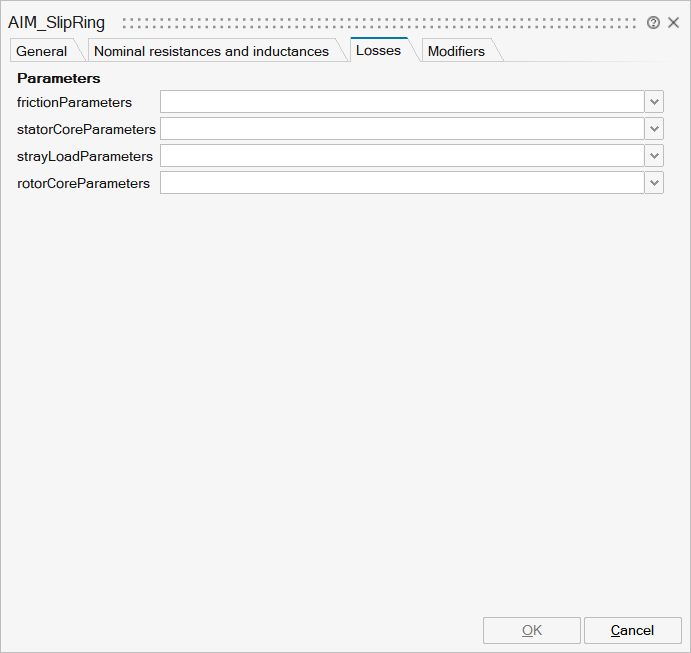
mo_frictionParameters | frictionParameters | Friction loss parameter record | FromModelica('Modelica.Electrical.Machines.Losses.FrictionParameters') | |
mo_statorCoreParameters | statorCoreParameters | Stator core loss parameter record; all parameters refer to stator side | FromModelica('Modelica.Electrical.Machines.Losses.CoreParameters') | |
mo_strayLoadParameters | strayLoadParameters | Stray load loss parameter record | FromModelica('Modelica.Electrical.Machines.Losses.StrayLoadParameters') | |
mo_rotorCoreParameters | rotorCoreParameters | Rotor core loss parameter record; all parameters refer to rotor side | FromModelica('Modelica.Electrical.Machines.Losses.CoreParameters') |
| Name | Label | Description | Data Type | Valid Values |
|---|---|---|---|---|
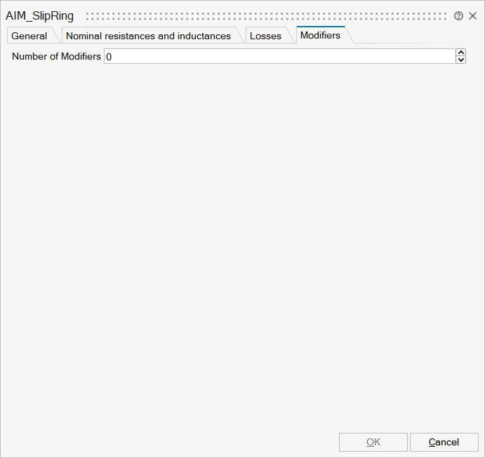
mo__nmodifiers | Number of Modifiers | Specifies the number of modifiers | Number | |
mo__modifiers | Modifiers | Add new modifier | Structure | |
mo__modifiers/varname | Variable name | Cell of strings | 'tauElectrical' | |
mo__modifiers/attribute | Attribute | Cell of strings | 'start' | |
mo__modifiers/value | Value |
Ports
| Name | Type | Description | IO Type | Number |
|---|---|---|---|---|
flange | implicit | Shaft | input | 1 |
plug_sp | implicit | Positive stator plug | input | 2 |
plug_sn | implicit | Negative stator plug | output | 1 |
plug_rp | implicit | Positive rotor plug | input | 3 |
plug_rn | implicit | Negative rotor plug | output | 2 |
Port 6 | implicit | Support at which the reaction torque is acting | input | mo_useSupport |
Port 7 | implicit | input | mo_useThermalPort |