Quick Mesh Setup
Introduction
Model browser can be used to do a quick mesh model setup. It can be performed by creating the Abaqus drop test / Structural / Thermal solution.
Mesh Parameters
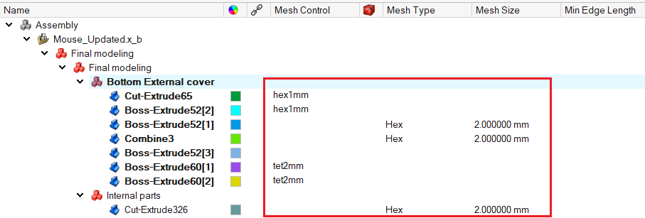
The following parameters can be defined in the model browser.
- Mesh Type: The element types available are Auto/Hex/Tet/Quad/Tri. The desired
mesh is obtained based on the chosen element type.In the case of Auto element type, the body meshes as follows:
- Solid - If possible Hex mesh, otherwise Tetra mesh.
- Sheet - Quad mesh.
- Mesh Size: The Mesh Size is the average element edge length for surface / solid elements. The element edge length will vary between (Mesh Size)*Sqrt(2) and (Mesh Size)/Sqrt(2).
- Min Edge Length: The Min Edge Length is used to remove all the elements that have element edges less than this value.
- Material: The Material for a body can be assigned using this column.
- Quality Spec: The quality criteria for a body can be assigned using this
column. The quality specification defined in
Custom XML is set automatically to the CAD bodies.
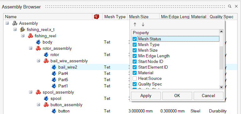
The following columns gives an overview of the output mesh:
- Mesh Status
 : A tick
mark in this column indicates successful creation of the mesh for the CAD
body.
: A tick
mark in this column indicates successful creation of the mesh for the CAD
body.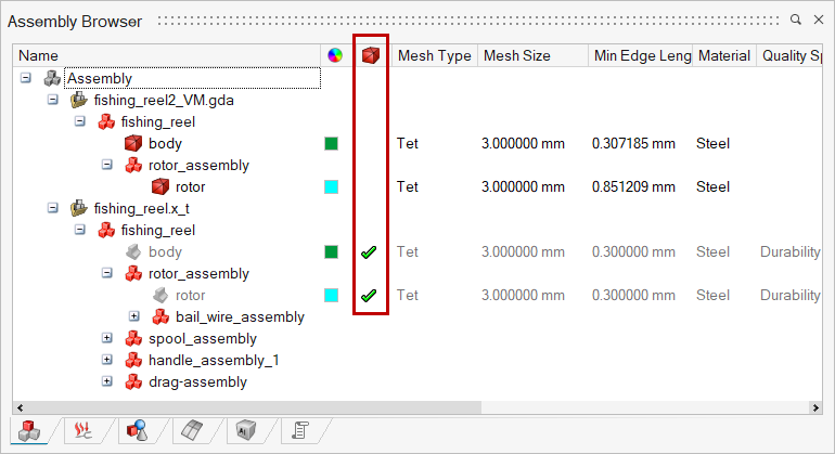
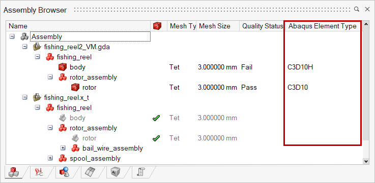
- Quality Status: This column indicates whether the assigned quality criteria are met or not by printing a Pass/Fail text.
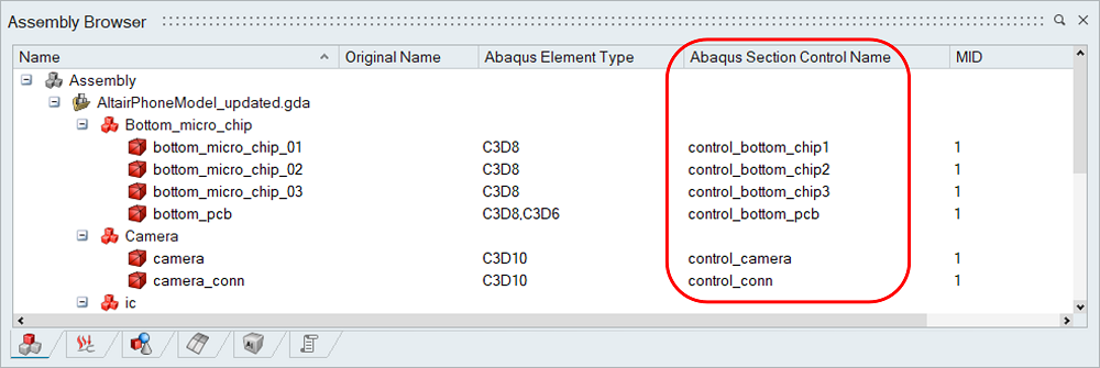
- Abaqus Element Type: This column displays the Abaqus element type of the
body based on the assigned property.Double-clicking this element type will open
the associated property dialog.
- Abaqus Section Control Name: User can define the control name for the
section card of the corresponding body using this column. The definition of the
*SECTION CONTROLS should be defined as a text data or should present in the
include file.
The following options are available for Right click on Model/Sub-Model/Body.
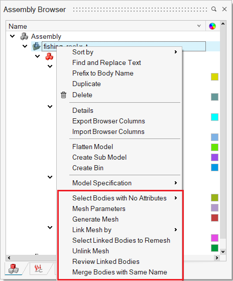
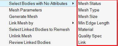
Select Bodies with No Attributes
This option is used to do a quick check for the bodies that do not have assigned with the required mesh parameters. In the case of mesh status, CAD bodies that do not have associated mesh bodies will get identified.
Mesh Parameters
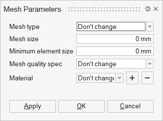
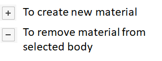
This tool helps to assign the needed parameters for the mesh model setup.
It is not mandatory to give all the parameters. The set/edited parameters alone get assigned or updated to the selected bodies. For example, if the user provides only the mesh type and size, these parameters get set to the bodies, and the rest get skipped.
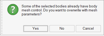
Quick mesh settings can be defined using mesh control or mesh parameters. When assigning mesh parameters and the body already has mesh control, a message gets prompted to overwrite or retain the current settings.
Generate Mesh
Select a model/sub-model/body to perform mesh. In the case of the CAD model, a new mesh model will get created and associated with the CAD model for the first time. All subsequent mesh for the CAD model will get added in this associated mesh model. The subsequent meshing of the same body will replace the old mesh body with the new mesh body.
Average element size is mandatory. SimLab assigns default values for other mesh parameters if a body doesn't have the mesh parameters or mesh control defined. User can specify their default values through Custom XML and, it gets considered for Tet and Tri mesh.
Identify Mesh Bodies to Link
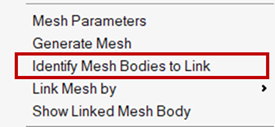
This tool assists in identifying nearby mesh bodies that can possibly be linked to the selected CAD body. It provides a list of mesh bodies based on proximity, allowing the user to review and manually establish links between the CAD body and the appropriate mesh body.
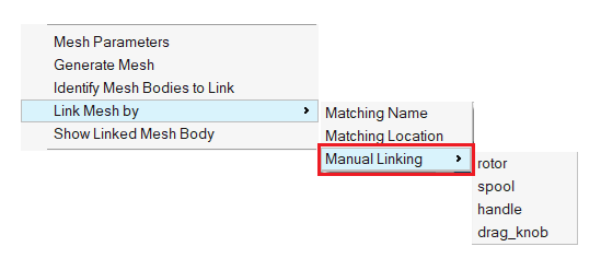
Link Mesh by
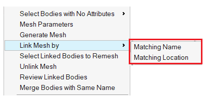
Using these options, users can reuse the existing deck/mesh of an old design to the upgraded/modified CAD file. Given the upgraded CAD, it automatically identifies the matching mesh bodies and creates an association between them. Once done, the user can easily find out the left-out cad parts and mesh them. This way, it helps to do quick modeling using existing reference mesh or deck files.
Matching Name
If the system could not automatically find the bodies, one can have the parts named consistent with the old mesh and use this option to create the association.
Matching Location
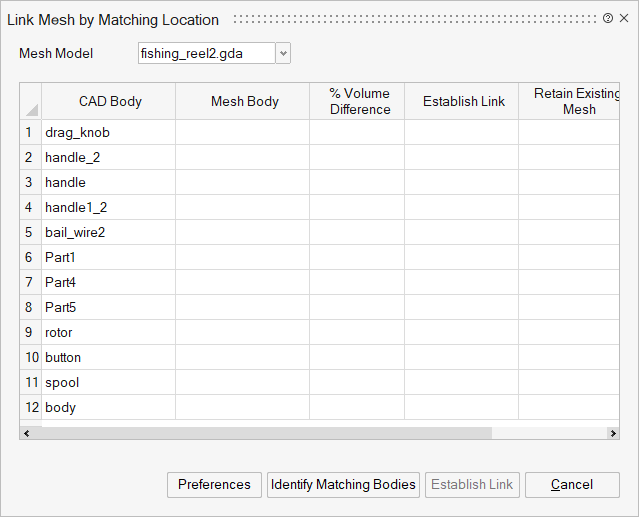
Identify Matching Bodies
For the given mesh model, this feature identifies mesh bodies that match with CAD bodies based on their position. Clicking a cell in the CAD / Mesh Body column filters the view to display only the corresponding bodies in that row.
If a CAD body does not have a corresponding mesh body, selecting its cell will isolate and display only that CAD body in the view.
Users can also use the arrow keys to navigate between cells.
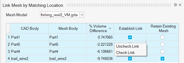
% Volume Difference
It shows the difference in volume between the CAD body and its associated mesh body. This column sort works based on absolute values.
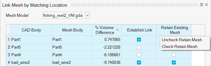
When selecting multiple rows, the user can toggle the 'Establish Link' and 'Retain Existing Mesh' options on or off using the right-click menu for the selected rows.
Establish Link column right-click options:
Retain Existing Mesh column right-click options:
Establish Link
By default, the Establish Link toggle is ON for all identified matching bodies. Users can toggle off the unwanted association. This option creates a link between the CAD and its mesh bodies. In the browser, the link column shows the icon for the CAD and its associated mesh bodies. Click this icon to get its associated body.
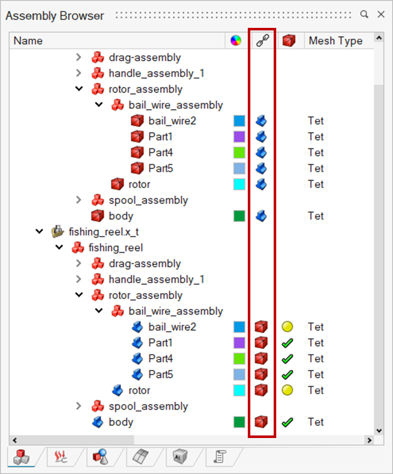
When linking an upgraded or modified CAD body to the mesh from a previous iteration, this toggle allows to choose whether to retain the existing mesh or update it to reflect the new CAD design for the model setup.
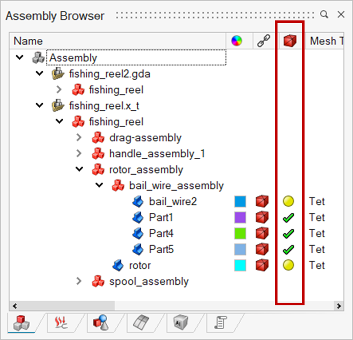
 The check mark
indicates that the existing mesh will be retained for the linked CAD body.
The check mark
indicates that the existing mesh will be retained for the linked CAD body.
 The circle indicates that
the mesh for this linked CAD body needs to be updated.
The circle indicates that
the mesh for this linked CAD body needs to be updated.
To identify the CAD bodies that require a mesh update, use the "Select Linked Bodies to Remesh" option by right-clicking on the Model, Sub-Model, or Body.
Thickness Change
Represents the difference in thickness between the CAD body and its corresponding mesh body. This parameter helps identify any variation introduced during meshing or simplification.
If both the CAD and mesh bodies are 2.5D, the thickness change is computed as CAD Thickness – Mesh Thickness.
A positive value indicates that the CAD body is thicker than the mesh body, while a negative value means the mesh body is thicker.
Centroid Shift
Represents the displacement of the centroid (geometric center) between the CAD body and its corresponding mesh body. This shift indicates how much the center of mass or geometry has moved due to meshing, simplification, or geometry modification.
A larger centroid shift may suggest a noticeable deviation between the CAD and mesh representations.
Preferences:
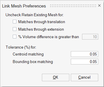
When working with a large number of parts, some may not align with their CAD locations, making it difficult to visualize and manually disable the 'Retain Existing Mesh' toggle.
The Preferences option allows you to set rules for automatically detecting parts that require a new mesh. These rules are applied during the identification of matching bodies, and the 'Retain Existing Mesh' toggle is set accordingly for the parts.
Manual Linking
This option allows linking the selected CAD body to a non-linked mesh body. All the available mesh bodies not linked to CAD bodies get listed in the context menu, and the user can choose the appropriate body to establish the link.
Unlink Mesh
This option breaks the association between CAD and Mesh bodies.
Review Linked Bodies
This tool helps to review the linked CAD and Mesh body details. All the link-established CAD and Mesh bodies are listed here, and the user can modify the needed data.
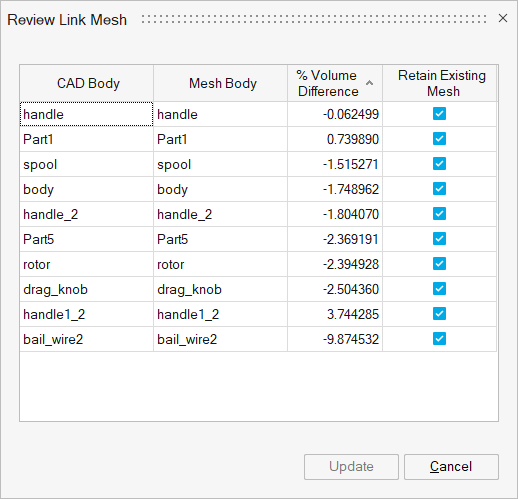
Clicking on the CAD / Mesh Body cell displays only those bodies.
% Volume Difference shows the difference in volume between the CAD body and its associated mesh body.
Retain Existing Mesh toggle specifying whether to reuse the mesh body or update it with the new CAD design for the model setup can be edited.
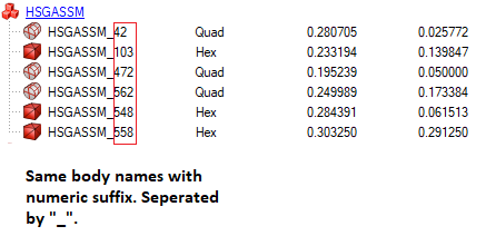
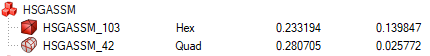
Merge Bodies with Same Name
This tool is used to merge the bodies having same names with difference in numeric suffix only. The bodies belonging to same type will get merged to one body.
- Before Merge
- After Merge
Link Selected Bodies
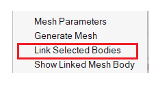
This option links the selected CAD and Mesh bodies if they don't have any existing links.
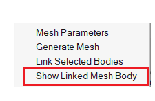
Show Linked Bodies
Show Linked Mesh Body / Show Linked CAD Body is used to find the linked CAD / Mesh bodies. In the case of CAD, it will find the associated mesh body, and in the case of Mesh, it will find its base CAD body.