This tutorial uses a special mapping for the hierarchical symbol to allow automatic extraction of the properties for inherited connectivity for the power and ground stubs.
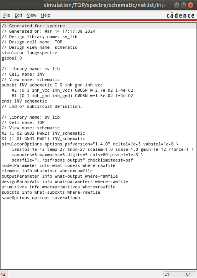
As an example, we use the Spice file demo/spice/invpwr.sp.
Please make sure that you have installed a license file which contains - in addition to one of the master GUI features - the feature gv-skillexport.
For an overview of the used concepts see the Skill Export tutorial.
FIRST STEP - Use Mapping For Inherit, Primitive And Hierarchical Symbols
After generating the symbol mapping templates with the help of the cadence2symlib.il script in Cadence Virtuoso, activate the desired mapping by removing the comment character # at the needed lines.
There are three different types of symbol mappings needed. One for the transistor devices, one for the I/O ports and one for the sub-circuit with the inherited connections.
In this tutorial, the transistor devices are mapped to nmos4 and pmos4 symbols from analogLib:
symlib 1.4 analogLib 178 16 37 i
spice nmos4 analogLib MN * w=W l=L
spice pmos4 analogLib MP * w=W l=L
...
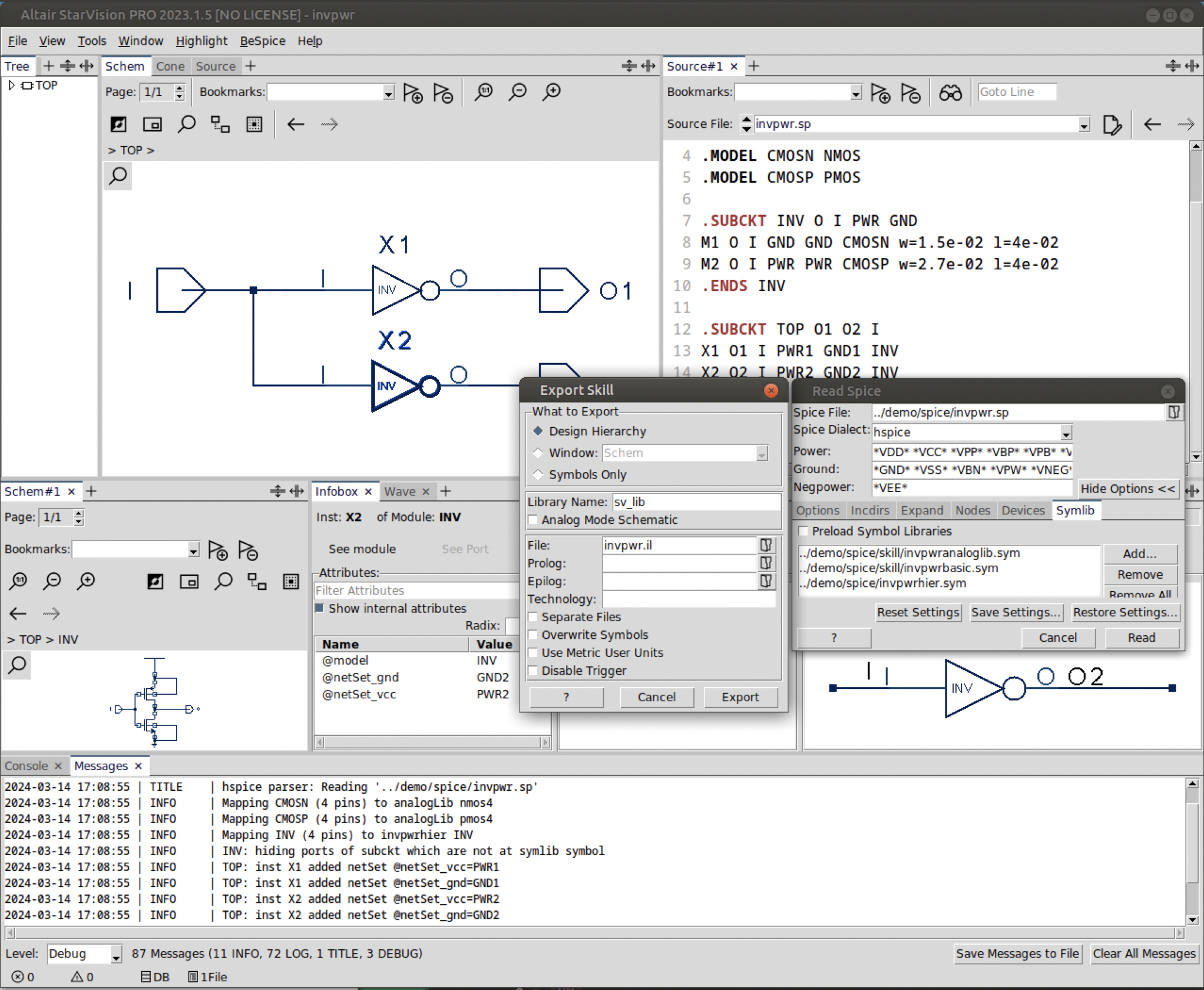
For the mapping of the interface ports the basic library is used. To show two different approaches here the power stub is mapped to an inherit power symbols from the basic library and an inherited connection via a netExpr properties, without a stub symbol for the gnd connection. Note the last value in the symio pg line, which defines the property names used for the inherited connectivity:
symlib 1.4 basic 82 16 35 i
symio ipin         in  * *   basic
symio opin         out * *   basic
symio vcc_inherit  pg+ * INV basic vcc
netexpr            pg0 * INV       gnd
...
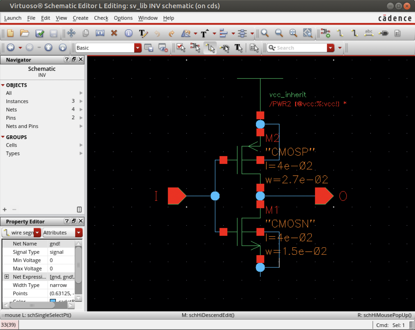
The symbol library containing the mapping of the hierarchical symbol can be found as demo/spice/invpwrhier.sym in the installation directory.
Please note that the power/ground port which exist in the spice subckt are missing in the symbol.
This will trigger the extraction of the connected nets into the properties needed for the inherited connectivity.
symlib 1.4 invpwrhier 6 16 22

symmap INV {} match INV

symbol INV * DEF \
   port I in -loc 0 -10 20 -10 \
   pinattrdsp @name -ll -2 -10 12 \
   port O out -loc 60 -10 48 -10 \
   pinattrdsp @name -ll 52 -10 12 \
   arc 40 -10 48 -10 40 -10 \
   path 20 -20 20 0 40 -10 20 -20 \
   attrdsp @cell -ll 22 -8 4 \
   attrdsp @name -lc 30 -24 12
A detailed description of the syntax of these lines can be found in the reference manual.
SECOND STEP - Load Design
As described in the Skill Export tutorial enable the visibility of all bulk pins, open the Read Spice dialog, add the symbol libraries containing the mappings for the devices, the I/O ports and the hierarchical symbol (invpwrhier.sym).
After reading the netlist, the invpwr.il Skill file can be generated.
THIRD STEP - Load Skill into Cadence
Load the Skill file you have created in the previous step, using the following input line of the Command Interpreter Window (CIW):
load("invpwr.il")
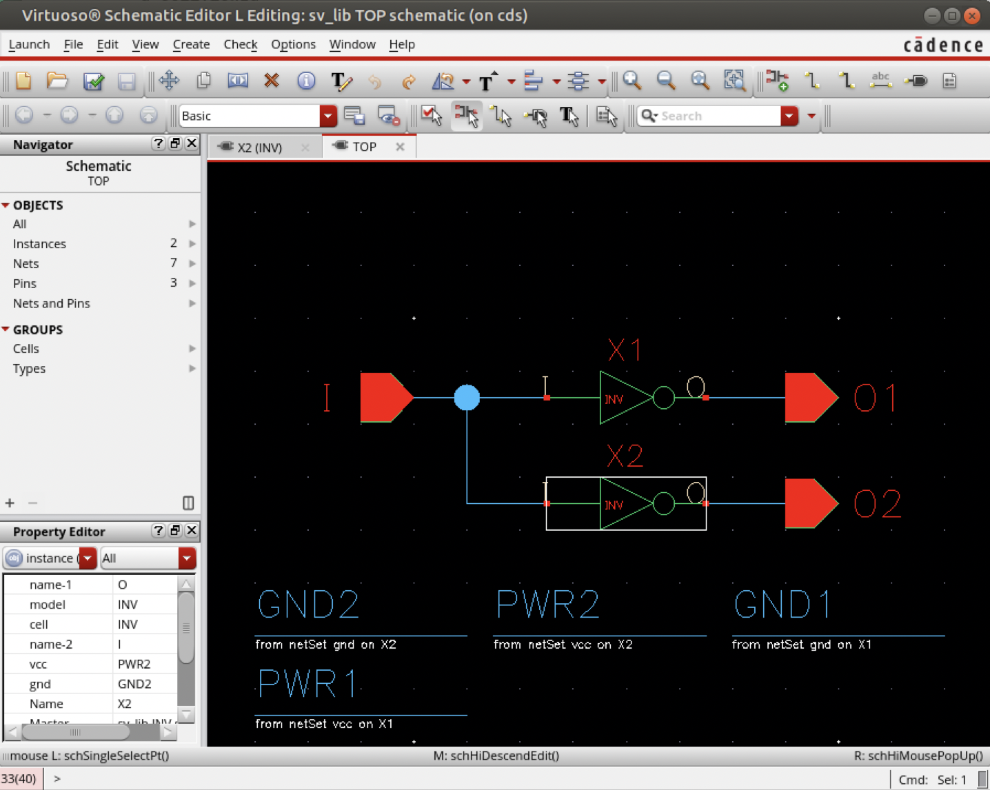
Use , select the library sv_lib, the cell TOP and the view schematic".
The use of will prepare the just created schematics.
The needed power and ground nets will be generated automatically.
The different netSet properties values for both instances can be inspected in the property editor (look for "vcc" and "gnd") here.
FOURTH STEP - Create Netlist
As described in the Skill Export tutorial, the netlist can be created to verify the correct inherited connections.