This tutorial discusses certain problematic cases with Spice circuits and their solutions - usually by adding input/output and power/ground information.
For standard cases, please refer to the Quickstart guide.
First Example
This example uses the demo file demo/spice/buf.sp to demonstrate how to add input/output information.
Read Spice
Press the  button in the toolbar to get the
 Read Spice dialog window.
To load a new Spice file, browse to the demo/spice/ directory and choose buf.sp.
Then press the Read button.
If the top level schematic is not generated automatically then double-click on the item "TOP" in the Tree window.
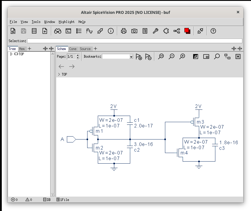
Generally, double-clicking a module in the Tree window makes it visible in the schematic window. This example has no hierarchy at all and therefore the Tree window only displays the top level module "TOP". Here is what you should see:
The Spice Parser Needs Help (Define "Additives")
The Spice Parser calculates (and sometimes guesses) some visualization information that is not directly available in Spice files.
This information is basically finding the power/ground and the input/output nodes.
In our current example buf.sp, the parser found the power and ground but did not manage to find any of the output ports.
You can manually add the missing information using the "Read Spice" dialog:
Define Input and Output
Press the button in the toolbar to get the Read Spice dialog window.
Press the Show Options button in order to switch to advanced mode.
Select the Nodes tab.
Select the output node (called Y) from the Schem window (by left mouse).
Now drag & drop the selected net over the Output button of the Nodes tab.
Please also check the Options tab in the Read Spice dialog window (advanced mode).
There, you can set some control switches, e.g. Ignore Capacitors will remove the capacitors below a given threshold value (or model name) from the schematic (can be useful if there are hundreds of parasitic capacitors).
Then press the Read button to load the Spice file again. This time the schematic has an output port and as a result the schematic is easier to read.
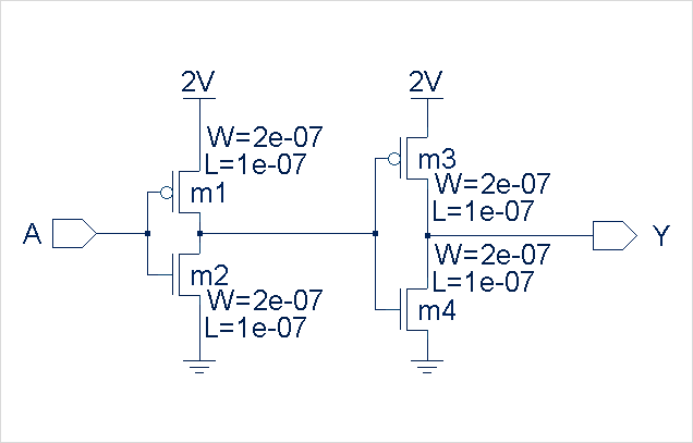
Now, you should see a schematic without capacitors and including the output port as in this picture. Please note, that you can save these parser settings in a "Project" file with the menu entry.
Second Example
This example uses the demo file demo/spice/adder.sp to demonstrate circuit hierarchy (dive down/up) and how to "navigate a signal through hierarchy".
Read Spice
Invoke to reset all design related settings to defaults.
Press the button in the toolbar to load the Read Spice dialog window.
Then load the Spice file adder.sp from the demo/spice/ subdirectory and press the Read button.
This example is hierarchy based. You can navigate in the Tree window by opening and closing the tree branches and double-clicking the module names or drag & drop items to one of the other views (Schem, Cone, Source or Mem).
Two more possibilities to traverse the hierarchy:
-
Double-click on an instance - a left-mouse double-click on a block instance in the Schem window brings you down one level of hierarchy. A press-drag-release to top left (with the stroke mouse button) dives up again.
-
Double-click on a pin (trace signal) - a left-mouse double-click on a pin of a block instance also brings you down one hierarchy level. In addition you will see the connected port highlighted so that it is very easy to analyze where the signal is connected on the new hierarchy level. A left-mouse double-click on the port dives up again.
After having dived down to the lowest level of hierarchy, you will see that only the NAND gates include transistor components (as in the picture below), all the other blocks just instantiate blocks.
Navigate Signal
Go to the TOP module and click on the  button in the toolbar to enable the Signal Mode.
Click with the right mouse button on the node 8, select Connectivity Browser from the popup menu.
In the new dialog you can select all pins/ports where this net is connected to.
If you double click an entry, the Schem window displays the selected component.
button in the toolbar to enable the Signal Mode.
Click with the right mouse button on the node 8, select Connectivity Browser from the popup menu.
In the new dialog you can select all pins/ports where this net is connected to.
If you double click an entry, the Schem window displays the selected component.
Third Example
This example uses the demo file demo/spice/csim90/gm1.sp.
It is very important for SpiceVision PRO to know the power and ground signals of a circuit.
Without detailed knowledge of power and ground signals SpiceVision PRO is likely to produce schematics that are not easy to read and in addition the schematic generation may take very long.
So please make sure that SpiceVision PRO knows about power and ground.
This example demonstrates how to modify "power" information in order to get the best possible schematic diagrams.
|
Note
|
The Spice file |
In this example, we assume that we don’t know the circuit very well and we will use SpiceVision PRO to find the correct settings.
Read Spice
Like in the previous example, execute to reset all values to defaults and press the button in the toolbar to get the Read Spice dialog window.
Choose demo/spice/csim90/gm1.sp and press the Read button.
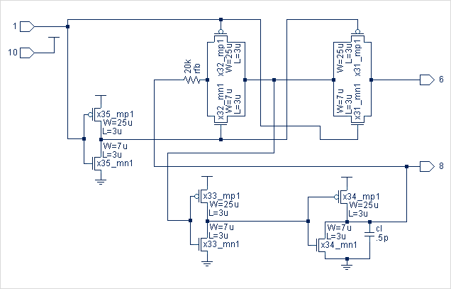
Visit the modules "TOP", "llatch", "dlatch" and "inv".
Please have a look at the inv schematic. You can see, that port 10 is an input but it should be a power signal. Now let’s change this so that we get schematic diagrams that are easier to understand. Here we manually define net 10 as power net.
Define Power
Press the button in the toolbar to get the Read Spice dialog window.
Press the Show Options button in order to switch to advanced mode.
Select the Nodes tab.
Go to the TOP module.
Find out that TOP’s net 10 connects to port 10 of each "inv".
Now drag & drop net 10 and drop it over the Power button of the Nodes tab.
(We do this on the TOP level, because SpiceVision PRO will derive power information down to sub-modules).
Press Read and visit the modules "inv", "llatch" and "dlatch" again.
This time most schematics look better since the SpiceVision PRO schematic engine was able to use power and ground information to generate better schematics.
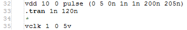
However, while "inv" and "llatch" look fine now, the "dlatch" now has another power node "1" that should be input. Here we need switch off the algorithm that evaluates power from DC voltage sources manually. Go to "TOP", highlight net 1 (e.g. select with left mouse button and press Ctrl+H) and go to line 35 in the Source window, then you’ll find:
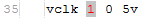
This indicates that node 1 is driven by a 5V DC voltage-source (see above).
Disable Automatic Power Evaluation
Press the button in the toolbar to open the Read Spice dialog again.
Go to the Options tab, uncheck the Evaluate VSource to: Power switch and press Read again.
Then again visit the modules "dlatch" and "TOP".
|
Note
|
A note on Power/Ground: There are three ways to define power and ground nets:
Whenever you want different defaults for Power/Ground (or for the other Spice options) just enter them and invoke the menu entry to get those values stored in a Project file. |
The "dlatch" schematic looks fine now, too, but there is one more SpiceVision PRO special that we can show with this example.
We can have SpiceVision PRO showing us expanded transistor structures rather than hierarchical symbols for the inv and tg blocks.
To do so, we add them to the Expand tab in the Read Spice dialog window:
Expand Blocks
Go to the "dlatch" module and select an inv and a tg instance.
Drag them with the left mouse button to the Add button of the Expand tab of the "Read Spice" dialog window.
Define Input and Output
Activate the Nodes tab of the Read Spice dialog window.
Drag the bidirectional port 6 from the Schem window with the left mouse button over the Output button.
Press Read and see how it looks (like the schematic below):
You can save the settings with into a .vpj file or - if you want to skip all the steps above - just open the existing project file demo/spice/csim90/gm1.vpj.
In addition to the settings above, demo/spice/csim90/gm1.vpj also defines the top-level nets 21 and 22 as output nodes.
Parasitic Filter
Learn how to hide all the parasitics capacitances/resistances below a certain value using the demo file demo/spice/amd2901.sp.
SpiceVision PRO provides two mechanisms to filter parasitics. Either the Spice Parser or a Pane window can filter the parasitics.
Each mechanism has its own advantage. The Spice parser discards the parasitics at parse time. This saves a lot of memory especially if you are not interested in parasitics at all. The Pane window filter keeps all the parasitics in the database and therefore lets you crossprobe from a filtered (functional) view to a full view including all the parasitics and vice versa. Both filters can be used in conjunction.
Spice Parser Filter
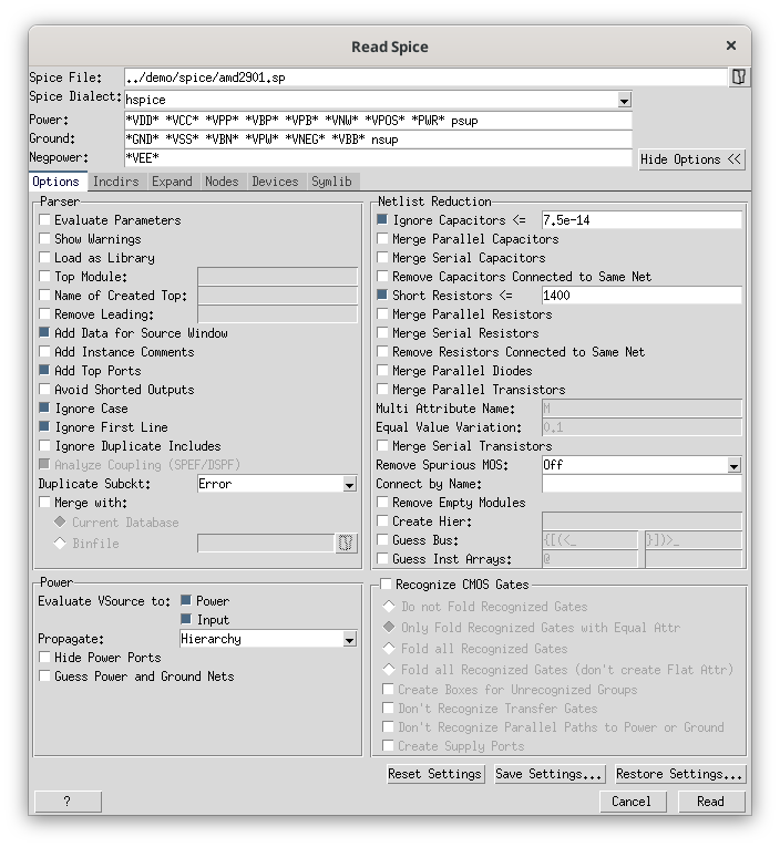
Start SpiceVision PRO, open the Read Spice dialog and browse to the Spice example demo/spice/amd2901.sp.
Now open the Advanced mode of the dialog window.
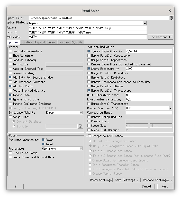
In the Options tab you can define the threshold value for the parasitic filter.
Press the checkbutton Ignore Capacitors and enter 7.5e-14 as the threshold value.
Also press the checkbutton for Short Resistors and enter 1400 as the threshold value.
Press the Read button to start the parser. Now all capacitors below 7.5e-14 Farad and all resistors below 1400 Ohm are ignored by the Spice parser.
Pane Window Filter
Start SpiceVision PRO, open the Read Spice dialog and browse to the Spice example demo/spice/amd2901.sp.
Press the Read button to start the parser.
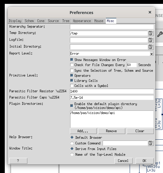
Open the Misc tab of the Preferences dialog to configure the parasitic filter.
Enter 1400 in the text entry after Parasitic Filter Resistor and 7.5e-14 in the text entry after Parasitic Filter Caps.
Press the OK button to apply the values and close the dialog.
To use the filter you need to open a new New Default Pane window from the Window menu (). In every newly created schematic (Schem or Cone window) all capacitors below 7.5e-14 Farad and all resistors below 1400 Ohm are filtered by the schematic engine.
Bulk Connection
Start SpiceVision PRO, open the Read Spice dialog and browse to the Spice example demo/spice/amd2901.sp.
Press the Read button to start the parser.
Expand the tree two times and double click on the module 'o3_x2' to display the schematic.
Locate the transistors Mtr_00002 and Mtr_00008.
Use the Search window if you cannot find the transistors.
These two transistors are displayed with a visible bulk because the pin is not connected to power or ground.
The bulk of all other transistors is not visible because the pin is connected to power or ground.
The default behavior of SpiceVision PRO is to display only wrong bulk connections. In the menu there are options to toggle the visibility of bulk and substrate pins:
-
Show Wrong Bulks- Show only bulk and substrate pins that don’t connect to their corresponding power supply. This is the default behavior. -
Show All Bulks- Show all bulk and substrate pins. -
Show No Bulks- Never show any bulk and substrate pin.
To find all wrong bulk connections in a design, you can run . All transistors with a wrong bulk connection will be listed in the Mem window.
Parallel Devices
Collapse parallel devices and have the sizes reflect the equivalent sizes or values for transistors, capacitors, resistors and inductors.
Start SpiceVision PRO, open the Read Spice dialog and browse to the Spice example demo/spice/csim90/mux8.sp.
Press the Read button to start the parser.
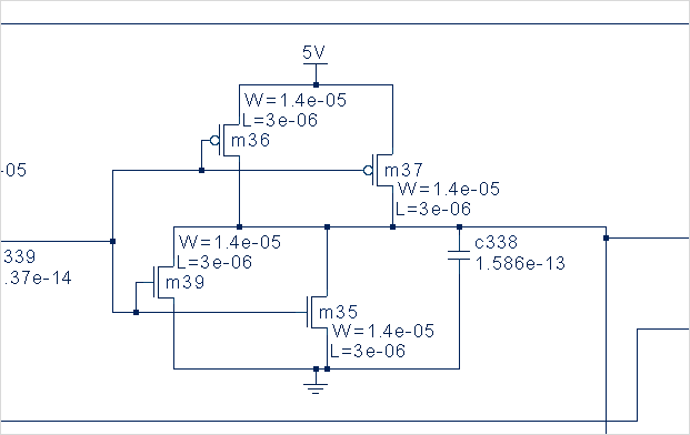
Locate the transistors m35, m36, m37 and m39.
Use the Search window if you cannot find the transistors.
The following image shows the parallel devices m36 and m37 as well as m35 and m39.
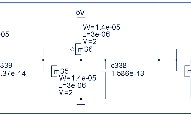
To collapse the parallel devices open the Read Spice dialog again in Advanced mode. Activate the check button Merge Parallel Transistors and press the Read button to reread the Spice file.
The Spice parser adds the extra attribute M to each transistor instance representing a group of parallel devices.
This attribute is now visible in the schematic view.
The following image shows the collapsed devices with the M-factor annotated (M=2).