
Structural Load Cases
Set up and edit structural load cases.
-
On the Structure ribbon, select the Structural tool or
double-click Setup
 for a structural load in the
Model Browser.
for a structural load in the
Model Browser.
Tip: To find and open a tool, press Ctrl+F. For more information, see Find and Search for Tools.Tip: Right-click the Load Cases folder in the Model Browser, select New Load Case, and select a load case type to create a new load case: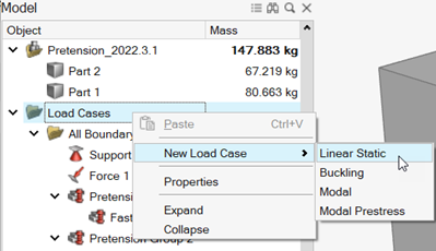 The Structural (Linear Static) or Structural (Linear Buckling) guide panel is displayed.
Figure 1. Linear Static Load Case 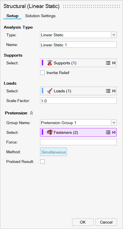
Figure 2. Linear Buckling Load Case 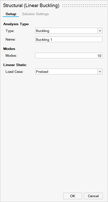
-
On the Setup tab, select an analysis type from the Type
dropdown.
Note: Buckling modes are used to predict when a part will bend or collapse under load. You may select the number of modes and which buckling load cases to include. The resulting buckling load factors help you determine the load required to cause your part to buckle. If the value is in-between -1 and 1, buckling is expected for the given load.
- Enter a name in the Name box to identify the load case.
-
For a linear static load, enter support parameters.
- Use the Supports collector and click the supports
you want to include in the load case. Selecting a load case will include
its supports.Tip: You can also select supports in the Model Browser.Note: Click Expand/Collapse
 to show or hide
the list of selected supports. If you need to remove a support,
right-click it and select Remove.
to show or hide
the list of selected supports. If you need to remove a support,
right-click it and select Remove. 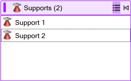
- Select Inertia Relief to apply inertia relief to all load cases. Supports will be ignored.
- Use the Supports collector and click the supports
you want to include in the load case. Selecting a load case will include
its supports.
-
For a linear static load, enter load parameters.
- Use the Loads collector to select the loads to
include in analysis. Selecting a load case will include its loads.Tip: You can also select loads in the Model Browser.Note: Click Expand/Collapse to show or hide
the list of selected loads. If you need to remove a load,
right-click it and select Remove.
- Enter a Scale Factor to apply scaling to forces.
- Use the Loads collector to select the loads to
include in analysis. Selecting a load case will include its loads.
-
For a linear static load, enter pretension parameters.
- Select a Group Name from the dropdown
list.Note: Each linear static analysis can include a single pretension group.
- Use the Fasteners collector to select the
fasteners where you want to include pretension force.Tip: You can also select loads in the Model Browser.Note: Click Expand/Collapse to show or hide
the list of selected fasteners. If you need to remove a fastener,
right-click it and select Remove.
- Enter a value in the Force box to specify the amount of pretension force.
- Select Simultaneous to apply force to all
fasteners at the same time. Note: When using SimSolid, forces are applied to all fasteners simultaneously. When using OptiStruct, loads are applied sequentially.
- Select the Preload Result checkbox to generate
additional results considering only fastener pretension.Note: A linear static load is limited to a single pretension group.
- Select a Group Name from the dropdown
list.
- For a buckling analysis, enter the number of Modes and select a Load Case from the dropdown.
- If you're using SimSolid as a solver, you can use the Solution Settings tab to refine SimSolid solutions.
-
Right-click and mouse through the check mark to exit, or double-right-click.
Note: When you analyze or optimize a model, all load cases are included. You can suppress loads that you don't want to include in a run.