
HelicalGearSet
Model ElementSpecifies a helical gear set. Construction of two paired helical gears.
Class Name
HelicalGearSet
Description
Attributes
The table below summarizes the attributes of the HelicalGearSet
classes.
| Variable | Type | Notes | Symbol |
|---|---|---|---|
| id | Int() | Unique identification number. | |
| label | Str() | Descriptor of the gear set element. | |
| rm | Reference("Marker", required=True) | The reference marker of the gear set element. This marker points to the center of gear 1. Defines the orientation of the gears (z axis of reference marker is the gear’s axial axis). | |
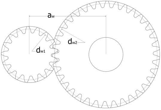
| rm_2 | Reference("Marker") | The reference marker of gear 2. This Marker needs to have the same orientation of the z-axis with the rm (axial direction), and its origin should be on the plane that is defined from the z axis of the rm (Inplane to the z axis of rm). The operating center distance is calculated from the two reference markers and is used as an input for the gear set. | |
| module | Double(required=True) | The normal module of the gear. | |
| num_of_teeth_1 | Int(required=True) | The number of teeth on gear 1 (see comments 5, 7). | |
| num_of_teeth_2 | Int(required=True) | The number of teeth on gear 2 (see comments 5, 7). | |
| gear_ratio | Double(required=True) | The gear ratio (see comments 5, 7). | |
| pressure_angle | Double(required=True) | The normal pressure angle in degrees. | |
| helix_angle | Double(required=True) | The helix angle at the pitch diameter in degrees. | |
| width_1 | Double(required=True) | The width of gear 1. | |
| width_2 | Double(required=True) | The width of gear 2. | |
| addendum_coefficient | Double(1.0) | The basic rack addendum coefficient. | |
| dedendum_coefficient | Double(1.25) | The basic rack dedendum coefficient. | |
| tool_tip_radius_coefficient | Double(0.38) | The basic rack tool tip radius coefficient. | |
| hub_diameter_1 | Double(0.0) | The inner/outer diameter of gear 1. | |
| hub_diameter_2 | Double(0.0) | The inner/outer diameter of gear 2. | |
| x1 | Double(0.0) | The profile shift coefficient of gear 1 (see comment 6). | |
| x2 | Double(0.0) | The profile shift coefficient of gear 2 (see comment 6). | |
| j1 | Double(0.04) | The circumferential backlash ratio of gear 1. The range should be (0.03 – 0.05) (see comment 2). | |
| j2 | Double(0.04) | The circumferential backlash ratio of gear 2. The range should be (0.03 – 0.05) (see comment 2). | |
| g1_connection_part | Reference(“Part", required=True) | The part that is connected to gear 1. | |
| g2_connection_part | Reference(“Part", required=True) | The part that is connected to gear 2. | |
| g1_connection_type | Enum("REVOLUTE FIXED ", default=" FIXED ") | The type of connection between gear 1 and the connected part. | |
| g2_connection_type | Enum("REVOLUTE FIXED ", default=" FIXED ") | The type of connection between gear 2 and the connected part. | |
| num_curve_segments | Int(10) | The number of mesh segments along the involute profile of each gear. When using non-uniform mesh, this parameter is always an even number (the profile is split into two symmetric regions). | |
| num_width_segments | Int(20) | The number of mesh segments along the width of each gear. | |
| non_uniform_factor | Double(1.2) | Defines the factor of the mesh’s non-uniformity. The length of a triamesh element is equal to the previous element length times this factor. Use 1.0 for a uniform mesh. | |
| density | Double() | The density of the gear's material (see comment 4). | |
| contact_creation | Bool(True) | Activates an IMPACT contact between the two gears (see Contact IMPACT). | |
| contact_stiffness | Double(1e5) | Specifies the stiffness parameter of the gear's contact (see Contact IMPACT stiffness). | |
| contact_exponent | Double(2.1) | Specifies the exponent of the force deformation characteristic of the gear's contact (see Contact IMPACT exponent). | |
| contact_damping | Double(1.0) | Specifies the maximum damping coefficient that is to be used for generating a damping force on the gear's contact (see Contact IMPACT damping). | |
| contact_dmax | Double(0.1) | Specifies the penetration at which full damping is applied in the gear's contact (see Contact IMPACT dmax). | |
| contact_coulomb_friction | Enum("ON OFF DYNAMICS_ONLY", default="OFF") | Specifies the friction force model that will be used to compute the gear's contact friction force (see Contact IMPACT coulomb_friction). | |
| contact_mu_static | Double(0.2) | Defines the coefficient of static friction in gear's contact when the friction is in the static regime (see Contact IMPACT mu_static). | |
| contact_mu_dynamic | Double(0.1) | Defines the coefficient of dynamic friction in gear's contact when the friction is in the dynamic regime (see Contact IMPACT mu_dynamic). | |
| contact_stiction_transition_velocity | Double(1.0) | Defines the slip velocity at which the static coefficient of friction, mu_static, is applied (see Contact IMPACT mu_ stiction_transition_velocity). | |
| contact_friction_transition_velocity | Double(1.5) | Defines the slip velocity at which the dynamic coefficient of friction, mu_dynamic, is applied (see Contact IMPACT mu_stiction_transition_velocity). | |
| export_graphic | Bool(False) | Exports the gears' geometries to two *.stl files. These files can be re-meshed in HyperMesh. | |
|
export_parameters |
Bool(False) | Exports the calculated gear set and gear's parameters in a *.json file. |
Example
g = HelicalGearSet (
    id=1,
    label='Helical gear set',
    rm=Marker(part=ground),
    rm_2=Marker(part=B_Ground, qp=[center_distance, 0, 0], rm=rm),

    module=1.0,
    num_of_teeth_1=17,
    num_of_teeth_2=35,
    gear_ratio=2.06,
    pressure_angle=20.0,
    helix_angle=15.0,
    width_1=10.0,
    width_2=9.0,

    addendum_coefficient=1.0,
    dedendum_coefficient=1.25,
    tool_tip_radius_coefficient=0.38,

    hub_diameter_1=0.0,
    hub_diameter_2=0.0,

    x1=0.2,
    x2=-0.1,

    j1=0.04,
    j2=0.04,

    g1_connection_part=B_Ground,
    g2_connection_part=B_Ground.

    g1_connection_type='FIXED',
    g2_connection_type='FIXED',

    num_width_segments=20,
    num_curve_segments=10,
    non_uniform_factor=1.2,

    density=7.85e-06,

)