To understand rigid body stoppers, compare the configuration of an actual press to that of a simulation.
The image below illustrates a standard press configuration, which includes:
| 1. | A punch or post that is fixed to the ground |
| 2. | A lower binder mounted on air-springs or nitrogen cylinders |
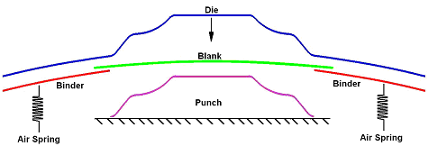
A conventional press setup
In reality the die moves down and clamps the blank between itself and the binder. The springs (or nitrogen cylinders) act only in compression. They resist the motion of the die until the force exerted by the die moving downward exceeds their stiffness.
In simulation the effect of the air springs on the binder is represented using a force load. This force load is applied to the binder at the beginning of the simulation, which is shown in the following image.
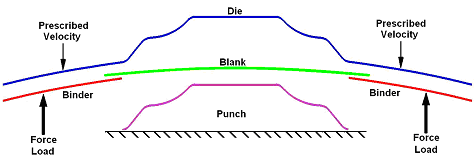
Simulation using loads
By applying a force load to the binder, it becomes necessary to limit the displacement of the rigid body so that it does not move upward unrestrained at the beginning of the simulation. Additionally, while the binder is moving, significant inertial effects can result between the blank and tools. These inertial effects are not desirable behavior because they generally do not occur in reality. To help address this problem, the binder can be modeled using constraints that limit the displacement and maximum velocity of a rigid body. The constraints, called "rigid body stoppers" in LS-DYNA, are a modeling technique that can help improve the behavior of the tools. To set up tools using rigid body stoppers, go to the Tool Loads panel in HyperForm.
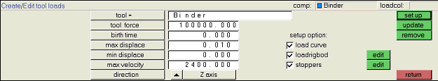
The Tool Loads panel in HyperForm
As an example, a load of 100000 N is applied to the binder in the Z direction at the beginning of the simulation. To prevent the binder from moving up due to the load, the binder is constrained using a maximum displacement of 0.01 mm. This constraint restricts the binder from moving up more than 0.01 mm.
A maximum velocity limit is applied to the binder. In this case, the maximum velocity limit is chosen to be 2400 mm/s. If the prescribed die velocity is 2000 mm/s, the max velocity limit for the binder is calculated to be 1.2 times the die velocity. Using a velocity limit slightly larger than the velocity on the die allows the binder to move with the die. This allows for small adjustments due to thickening and wrinkling that might occur in the blank.
In summary, the use of rigid body stoppers compensates for inaccuracies that are created by the modeling approach, and allows the simulation to give much more realistic results.


