
Identify Parts
Use the Identify Parts tool to define types of parts like wheels, heat exchangers or body panels, which require specific modeling techniques for the CFD run. During import, all parts are identified as body by default. This applies a zero-velocity wall boundary condition for the CFD analysis. Besides the default Body identification, the Identify Parts tool allows you to identify parts as a Heat Exchanger, Wheel or Fan.
Wheels
When modeling a wheel, a wall boundary condition is prescribed, and – when the Rotating wheels option is enabled () – a rotational velocity – based on the distance from the axis of rotation to the ground – is applied. Once you select the parts forming the wheel assembly, parameters like the center of rotation, axis of rotation, and angular velocity (in RPM) are computed automatically (these may be overwritten by the user by disabling “Auto Calculate” – see Step 6). If multiple parts are selected, the parts will be grouped into one or more wheels. For example, if you select the brake disc, the rim and the tire of the left front wheel, all three parts will be identified as wheel_1. If you also select the rim and the tire of the left rear wheel, those parts will be grouped into wheel_2.
Identification
-
To view only the parts that make up the wheels, you will need to hide the rest
of the parts.
- In the , select the Wheels assembly.
- Right-click and select Isolate from the context menu or press I to isolate the wheel geometry.
-
From the Setup ribbon, click the Identify
Parts tool.
Figure 1. 
-
From the secondary tool set, click the Create Wheel
tool.
Figure 2. 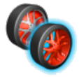
-
Select all Wheels parts.
Figure 3. 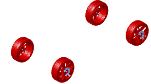
- Click on the parts now identified as wheels in the Model Browser.
- In , ensure that Auto Calculate is enabled.
- Press Esc or right-click in empty space to exit the tool once all the wheels have been identified.
Rotating Wheels
-
From the Setup banner click on the Run tool.
Figure 4. 
- From the setup micro-dialog, under Analysis setup, enable Rotating wheels (it is enabled by default). If left unchecked, the wheels will be identified as such, but a zero velocity non-slip boundary condition will apply.
Moving Reference Frame (MRF) Wheel Setup
Moving Reference Frame (MRF) regions define a volume in which the governing equations are solved in a rotating reference frame. This transformation of the equations can lead to higher accuracy for rotating bodies due to the addition of centrifugal and Coriolis forces. A closed volume of revolution (VREV) is generated in HMCFD for each MRF region.
- If parts other than the wheels are currently displayed, isolate the wheels by repeating Step 1.
- From the Setup ribbon, click the Identify Parts tool.
-
From the secondary tool set, click MRF tool. A guide bar appears below the
tool.
Figure 5. 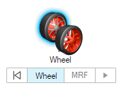
-
Click on any part of the front-left wheel which was identified as
Wheel in steps Step 1-5.
The entire wheel group is selected.
- From the Model Browser, select and Show the part named VREV_Wheel_Spokes_Front_Left.
- On the guide bar, click MRF.
-
From the display window, click on
VREV_Wheel_Spokes_Front_Left (the disk on the
front-left wheel) to identify it as the MRF region.
Figure 6. 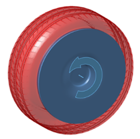 The region is highlighted blue.
 - Click Play on the guide bar to confirm your selection.
- Repeat the above process for the other wheels, using their respective VREV parts.
-
From the Model Viewer, isolate the
Main assembly to show the full vehicle model.
Tip: Use the Tab key to cycle between Wheel and MRF selections. Click Back on the guide bar to clear a selection.
- The angular velocity and center of rotation of the rotating frames are extracted from the wheel definitions. Tip:
Overset Mesh (OSM) Region Wheel Setup
Overset Mesh (OSM) Regions define a volume in which all voxels and surface elements contained within are rotated about its axis. This transformation of the geometry can lead to higher accuracy for rotating bodies as it more closely approaches the intended state as compared to wall velocity BC and MRF methods. A closed volume of revolution (VREV) is generated in HMCFD for each OSM region.
Due to reasons related to legacy, the OSM workflow utilizes the Fan identification tool.
- If parts other than the wheels are currently displayed, isolate the wheels by repeating Step 1.
- From the Setup ribbon, click the Identify Parts tool.
-
From the secondary tool set, click Fan tool. A guide panel appears, and a
selector tool is activated.
Figure 7. 
- Click on the Wheel_Spokes_Front_Left part.
- From the select Overset.
- From the Model Browser, select and Show the part named VREV_Wheel_Spokes_Front_Left.
- From the Fan Guide Panel, press the Select button.
- From the display window, click on VREV_Wheel_Spokes_Front_Left (the disk on the front-left wheel) to identify it as the OSM region. The region becomes transparent.
- Flip the rotation of the OSM region to match that of the wheels by pressing the +/- button in the Axis micro-dialog.
- From the Axis micro-dialog, set the RPM to 1031.569 to match the auto-calculated RPM of the wheels. Alternatively, you may edit the RPM value from the Property Editor.
-
From the Fan Guide Panel, enable Mesh
Controls and set the Refinement Level
value to 6.
This will ensure that voxels within the OSM Region are at most the size of Resolution Level 6 (RL06) voxels.
-
From the Fan Guide Panel, enable Interface
Refinement and set the Refinement Level
value to 7. This will ensure that voxels along the
interface (as represented by the elements of the VREV part) of the OSM Region
are at most the size of Resolution Level 7 (RL07) voxels.
Note: In certain cases – most commonly when dealing with high performance vehicle – the gap between the wheel spokes and the brake caliper may be small enough to require higher resolution at the interface. As a rule of thumb, you should aim to fit a minimum of 9 voxels in this gap: 6 from the surface of the spokes (the rotating geometry), and 3 from the surface of the caliper (the stationary geometry). You should never fit less than 4.5 voxels from the rotating geometry and/or 1.5 voxels from the static geometry.
- Click Play on the Fan Guide Panel to confirm your selection.
- Repeat the above process for the other wheels, using their respective VREV parts.
-
From the Model Viewer, isolate the Main assembly to show the full vehicle
model.
Note: The split intersecting part option included in the Fan Guide Panel was not used here because the parts used in this example were already split in the Geometry Repair environment of HMCFD prior to transferring the model to the Case Setup environment. This is the recommended process. Please refer to the Geometry Report portion of the External Aerodynamics Tutorial for details on how to perform these operations.
Heat Exchangers
-
To view only the parts that make up the heat exchangers, you will need to hide
the rest of the parts.
- In the , select the Porous_Media assembly.
- Right-click and select Isolate from the context menu or press I to isolate the wheel geometry.
- From the Setup ribbon, click the Identify Parts tool.
-
From the secondary tool set, click the Heat Exchanger
tool.
Figure 8. 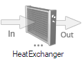
-
The Heat Exchanger Inlet Selection Tool should be
automatically selected. If it is not, click on the In
arrow of the Heat Exchanger Tool.
Figure 9. 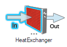
- From the graphics area, click on the part named Porous_Media_Transmission_Oil_Cooler_Inlet to identify it as the inlet of that heat exchanger.
-
Click on the Heat Exchanger Wall Selection Tool.
Figure 10. 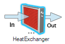
- Click on the part named Porous_Media_Transmission_Oil_Cooler_Walls to identify it as the wall of that heat exchanger.
-
Click on the Heat Exchanger Outlet Selection Tool.
Figure 11. 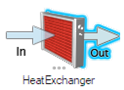
- Click on the part named Porous_Media_Transmission_Oil_Cooler_Outlet to identify it as the outlet of that heat exchanger.
-
Create a second heat exchanger by clicking the plus button in the Heat
Exchanger Dialog.
Figure 12. 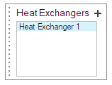
- Repeat Steps 4-10 to setup the other two heat exchangers.
- Press Esc or right-click in empty space to exit the tool.
- From the Model Browser, select each part identified as heat exchanger. From the Property Editor, enter 100 in and 300 in . Repeat this step for the other two heat exchangers.
-
From the Model Viewer, isolate the Main assembly to show
the full vehicle model.
Note: If a heat exchanger is not split into separate Inlet, Outlet, Wall parts, you may identify all its parts as Inlet. However, since the direction won’t be auto-calculated, you will have to enter the flow direction vector in the Property Editor under Permeability Direction.