All machines
Physics properties of Flux model are not well defined
The face region associated with a solid region - built with solid material - is not well defined in the physics properties of the Flux model.
A solid region is defined as a “Laminated magnetic non conducting” region instead of “magnetic non-conducting region”.
Features available in beta mode
Sometimes, a new test is provided in beta mode, meaning that it is not entirely qualified. However, we make it available for testing, and we invite the users to give us their feedback and comments for improving this feature even more.
To indicate the “Beta mode” status of the test, “BETA VERSION” is written in the overview of the considered test, as illustrated below.
For information here is the list of the features available in beta mode in the current version of FluxMotor:
- The process for importing parameterized part (inner magnet) from SimLab sketcher is in beta mode.
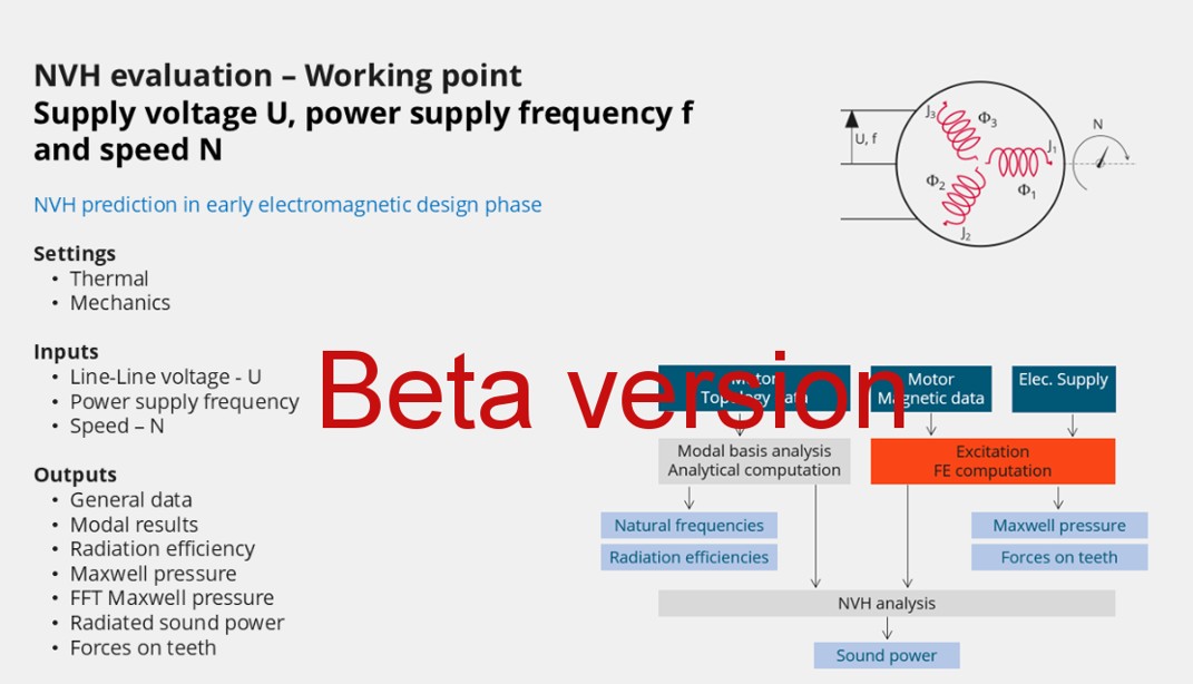
- Test – Mechanics – NVH – Working point If, I, PSI, N
- Test – Mechanics – NVH – Spectrogram If, I, PSI, N
- Test – Characterization - Model – Motor – Scalar
- Test – Performance mapping – Sine wave – Motor – Ems U-f (Efficiency map)
- Test – Performance mapping – Sine wave – Motor – Ems U-I (Efficiency map)
- Test – Mechanics – NVH – Working point U, f, N
- Test – Mechanics – NVH – Working point I, f, N
- Test – Mechanics – NVH – Spectrogram U, f, N
- Test – Mechanics – NVH – Spectrogram I, f, N
- Test – Working point – Constant speed – Motor & Generator – U-N
- Export – Flux 2D – Transient – Working point – Voltage source – Motor & Generator – Constant speed
The online user help guide is not yet updated
Considering the huge work done for improving the GUI and workflow for all the FluxMotor applications, the online
user help guide will be updated regularly after the release of FluxMotor 2026. We will do our best to complete this task as soon as possible.
Winding – Expert mode – defining of several circuits per sector
In Expert mode, several parallel circuits can be defined in a sector, and moreover, several coils can be built in one circuit.
Such circuits can be connected in parallel according to the user’s input No. parallel paths.
In that case, it is mandatory to balance all the parallel paths well while building and connecting the coils inside all the circuits.
Frame convection coefficient differences when estimated in Design External Cooling and in thermal tests
Frame convection coefficients (both natural and forced) estimated during the design phase and those obtained from thermal testing may diverge. This discrepancy arises because the empirical correlations used in the design do not account for the final surface and fluid temperatures reached during testing. Additionally, slightly different correlations are applied in the design and test contexts. This divergence will be addressed and corrected in future releases.
Natural convection for end winding
While choosing a model where the end spaces are cooled with natural convection, the FluxMotor® model uses quite a low rotor tip speed ratio (a value of 5) to describe the fluid velocity far from the rotating components. This may lead to an overestimation of the cooling of the end winding on high-speed machines.
When a tip speed ratio of 5 seems to overestimate the end winding cooling, it is advised to switch to forced convection mode.
This mode allows forcing some higher tip speed ratios for areas far from the rotor but reduces the efficiency of the cooling on the end winding.
This model will be improved for future versions.
Modification of units
To take the change of units into account in a test, the user must reopen Motor Factory. The modification is not considered instantaneous in applications of Altair FluxMotor® like Motor Factory.
Export a model into Flux® environment with represented elementary wires.
- Building time of the model in Flux®
When slots are filled out with a lot of elementary wires, and all the phases need to be represented with solid conductors inside the Flux® 2D model, the resulting python file can be very long. Therefore, the process of building the corresponding model in the Flux® environment can take a longer time.
Browse function
Sometimes, opening a folder from FluxMotor® applications via the browser function requires a longer time (several seconds).
Export environment – HyperStudy®
- Compatibility of HyperStudy connectors with respect to FluxMotor solver
versions
The process that describes how to update the HyperStudy connector is written in the user help guide “MotorFactory_Introduction.pdf”
- New test and connectors for HyperStudy®
Connectors for coupling FluxMotor® and HyperStudy® are not yet available for the newly added tests, like those with transient thermal computations or the tests for induction machine like the “Characterization – Model – Motor – Scalar” and the “Performance mapping – Sine wave – Motor – Efficiency map scalar”.
Mandatory synchronization between connector and FluxMotor versions
The connectors used in HyperStudy must be synchronized with the FluxMotor solver version.
An error message (inside the log files) is generated while performing HyperStudy studies with a connector provided with a former version of the FluxMotor solver.
Problems with slot filling
- Slot filling is not yet possible with a non-symmetric parallel slot.
-
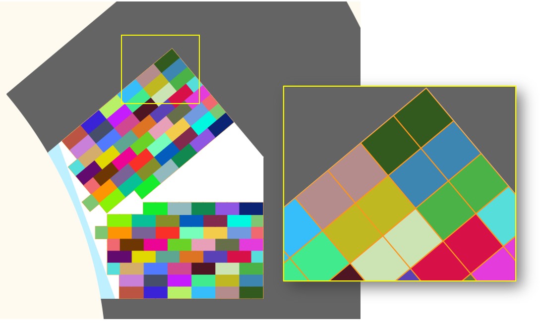
When a toothed winding design is considered with rectangular shaped wires, the conductor grouping method "horizontal" doesn’t work properly, leading to the wrong visualization of conductors. In that case, it is recommended to select the conductor grouping method "vertical".
All work well with circular shaped wires.
Example with a toothed winding design (i.e., the coil pitch = 1) and with 2 wires in hand.Figure 2. Horizontal filling – wrong visualization, but the total number of wires is right 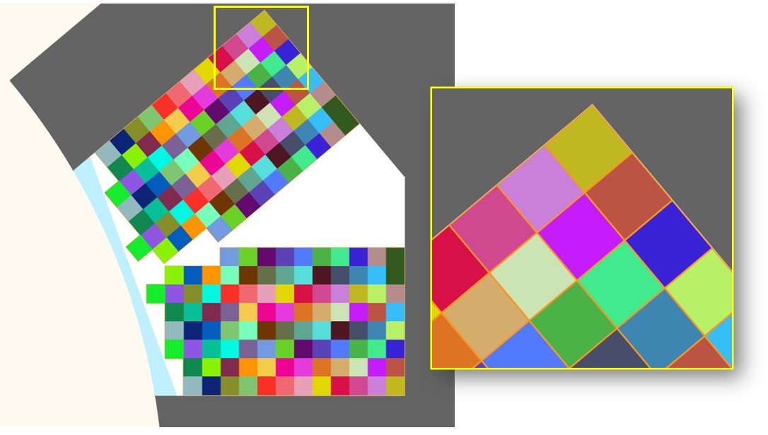
NVH computations - Advice for use
The modal analysis and the radiation efficiency are based on analytical computation, where the stator of the machine is considered a vibrating cylinder.
The considered cylinder behavior is weighted by the additional masses, like the fins or the winding, and the subtractive masses, like the slots and the cooling circuit holes.
This assumption allows for a faster evaluation of the behavior of the machine in connection to NVH. But in no way can this replace mechanical finite element modeling and simulation.
- The limits of the analytical model are reached or exceeded
- Unusual topology and/or dimensions of the teeth/slots
- Complexity of the stator-frame structure when it is composed of several components, for instance
- The ratio between the total length of the frame, Lframe and the stack length of
the machine, Lstk. In any case, this ratio must be lower than
1.5
Lframe/Lstk ≤1.5