I - Ψ - N
Positioning and objective
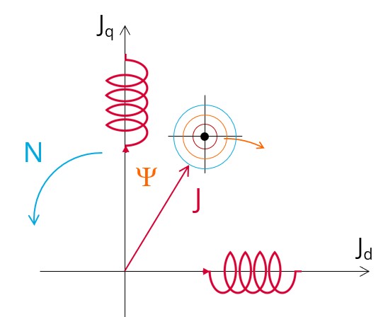
The aim of the test “Working point – Sine wave – Generator – I, Ψ, N” is to characterize the behavior of the machine when operating at the targeted input values I, Ψ, N (Magnitude of current, Control angle, Speed).
These three inputs are enough to impose a precise working point.
For instance, a working point on the efficiency map can be chosen, by identifying the current, the control angle and the speed with different curves or maps displayed in the “Performance mapping / Sine wave / Generator / Efficiency map” test. Then, the “Working point – Sine wave – Generator – I, Ψ, N” test allows to compute the performance for this working point.
The results of this test give an overview of the electromagnetic analysis of the machine considering its topology.
The general data of the machine, like machine constants, power balance and magnet behavior are computed and displayed. The generator convention is used to build the model.
The magnetic flux density is also computed in every region of the machine magnetic circuit to evaluate the design.
- The type of machine is Synchronous Machine with Permanent Magnets with Inner rotor.
- Iterative thermal solving modes can be selected.
- “Fast computation mode” is perfectly suited for the pre-design step (Hybrid model based on Magneto-Static Finite Element computations and Park transformation theory).
- “Accurate computation mode” is perfectly suited for the final design step (Pure Finite Element modeling based on transient computations).
It also gives the capability to make comparisons between the results obtained from the measurements and those obtained withFluxMotor.
The following table helps to classify the test “Working point – Sine wave – Generator – I, Ψ, N”.
| Family | Working point |
|---|---|
| Package | Sine wave |
| Convention | Generator |
| Test | I, Ψ, N |
Inputs
For more details, please refer to Inputs.
Thermal
For more details, please refer to Thermal.
Mechanics
For more details, please refer to Mechanics.