Fin
Type of fins
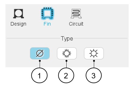
In this section, three choices are available to define the type of fin topology: None, Parallel, Radial.
By default, there is no fin. Fin type is set to “None”.
Important: Access to the “Fin” area is unlocked when a frame is defined
whose shape is circular or square.
Remember: The cooling device “Fin” is not available for outer rotor
topology.
 |
|
|---|---|
| 1 | Default setting: Fin type is « None ». The housing has no fin. |
| 2 | Button to select parallel fins. |
| 3 | Button to select radial fins. |
 |
|
|---|---|
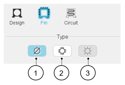
| 1 | Default setting: Fin type is « None ». The housing has no fin. |
| 2 | Button to select parallel fins. |
| 3 | Radial fins are not available when considering square shape housing. The corresponding button is greyed. |
Topology and dimensions
Parallel type fins
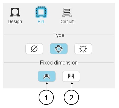
For the parallel type fins, two ways are possible to define the fin dimensions: "Height" and "Extension" options. See the illustrations below.
 |
|
|---|---|
| 1 | Button to select the parallel type of fin with constant height. |
| 2 | Button to select the parallel type of fin with constant total extension. |
- Illustration of parallel fins with constant height – Inputs
Table 4. Parallel type fin with constant height - Inputs 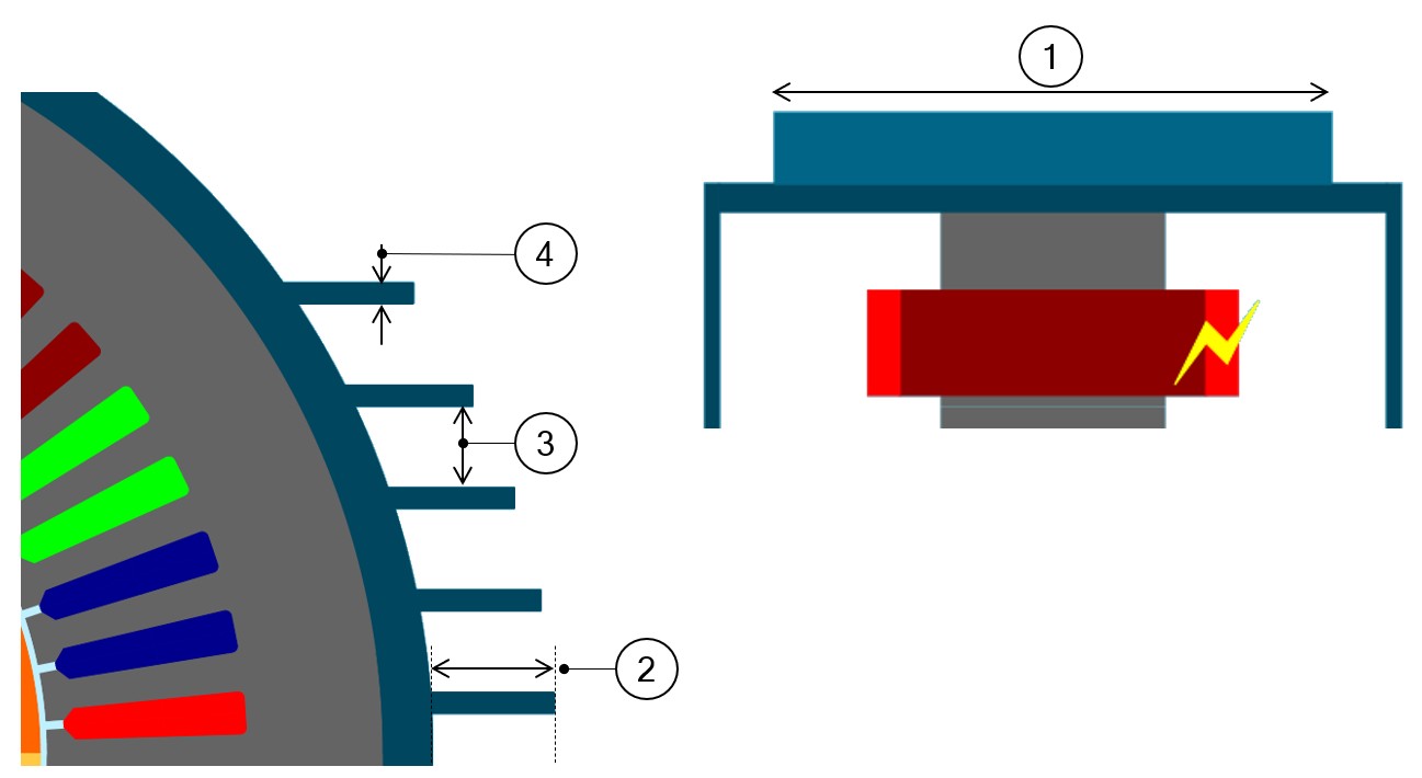
# No. fins (Number of fins) which spread all around the housing – Minimum allowed value = 12. 1 Fin length 2 Fin height 3 Inter-fin space 4 Fin thickness - Illustration of parallel fins with constant total extension –
Inputs
Table 5. Parallel type fin with constant total extension - Inputs 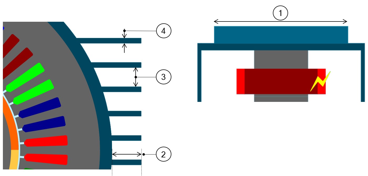
# No. fins (Number of fins) which spread all around the housing – Minimum allowed value = 12. 1 Fin length 2 Fin extension 3 Inter-fin space 4 Fin thickness
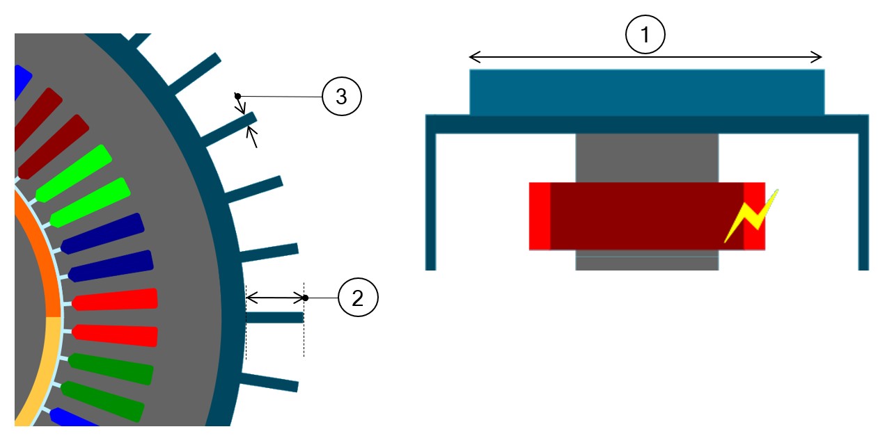
Radial type fins
 |
|
|---|---|
| # | No. fins (Number of fins) which spread all around the housing – Minimum allowed value = 12. |
| 1 | Fin length |
| 2 | Fin height |
| 3 | Fin thickness |