Winding
Overview
This kind of winding architecture is used by DC machines to define rotor winding.
The DC winding has a lot of similarities with the 3-phase winding but also many specific traits when referring to architecture.
Therefore, only the architecture is described in this section since the coil, insulation, end-winding and x-factor tabs do not have any important modification when compared with the 3-phase classical winding.
For further information regarding basic knowledge and terminology about electrical winding, please refer to the previous sections, which are dedicated to the winding design general user information.
Here is the homepage for the design of the rotor winding.
Design
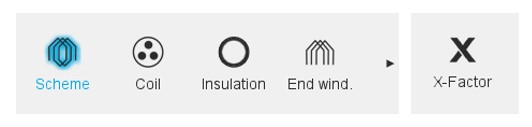
A scrolling selection bar helps to choose the section in which one can define the winding settings.
- “Scheme” to build the winding architecture.
- “Coil” to set how the coil is defined.
- “Insulation” to define all the winding insulations.
- “End winding” to define the dimensions of the end-windings.
- “X-Factor” to adjust phase resistance and end-winding inductance.
Terminology
Refer to the section “Terminology – Illustration” dedicated to DC winding.
Classical winding outputs
Please refer to the section “Winding / Winding outputs” dedicated to DC winding.