Block Category: Real Time
Description: The frequency block is based on the 9513 chip. Any board based on that chip can use the frequency block. Currently, these boards include:
|
Vendor |
Board |
|
Analog Devices |
RTI 815 |
|
Measurement Computing |
CIO-CTR05 |
|
Measurement Computing |
CIO-CTR05/H50 |
|
Measurement Computing |
CIO-CTR10 |
|
Measurement Computing |
CIO-CTR10/H50 |
The frequency block lets you access and read a particular channel on the 9513 counter and use the value of this signal in a diagram. Functionally, the frequency block performs the reverse options of the PWM block.
To obtain an accurate measurement, set the sampling interval (that is, the simulation time step) larger than the sample interval of the events you are measuring.
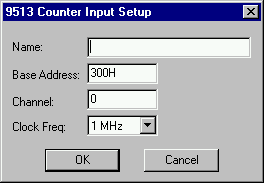
Base Address: Indicates the I/O port register address through which the real-time driver commands the board. Enter the base address as a hexadecimal number, followed by an “H.”
Channel: Indicates a number that corresponds with the channel number on the screw terminal or termination panel supplied with your I/O board. Embed uses channel 0 as the first channel, even if the documentation supplied by the board vendor describes the first channel as channel 1.
Clock Freq: Indicates a value that corresponds with the base frequency crystal value set on your I/O board. If the value you enter does not match the base frequency crystal value, erroneous results are produced.
Name: Specifies a unique name for your frequency block. By naming frequency blocks, you reduce the risk of misreading your diagram, particularly when you are using more than one frequency block.