Block Category: Real Time
Inputs:
•Freq and %duty Cycle: Combined, these two inputs form a signal with the specified frequency and duty cycle. The duty cycle indicates the percentage of time the signal is in an ON state. The PWM block sends the signal to the specified channel on the 9513 counter output.
Although you can dynamically change the input values simultaneously, you typically vary one or the other input at a time. For example, for power modulation, keep the frequency fixed at a constant value while varying the pulse width. Conversely, for pure frequency output, fix the pulse width and vary the frequency.
Description: The PWM block is based on the 9513 chip. Any board based on that chip can use the PWM block. Currently, these boards include:
|
Vendor |
Board |
|
Analog Devices |
RTI 815 |
|
Measurement Computing |
CIO-CTR05 |
|
Measurement Computing |
CIO-CTR05/H50 |
|
Measurement Computing |
CIO-CTR10 |
|
Measurement Computing |
CIO-CTR10/H50 |
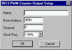
The PWM block defines the base address and channel number to which the pulse width modulated waveform is sent.
Base Address: Indicate the I/O port register address through which the real-time driver commands the board. Enter the base address as a hexadecimal number, followed by an optional “H.”
Channel: Enter a number that corresponds with the channel number on the screw terminal or termination panel supplied with your I/O board. Embed uses channel 0 as the first channel, even if the documentation supplied by the board vendor describes the first channel as channel 1.
Clock Freq: Enter a value that corresponds with the base frequency crystal value set on your I/O board. If the value you enter does not match the base frequency crystal value, erroneous results are produced.
Name: Specifies a unique name for your PWM block. By naming PWM blocks, you reduce the risk of misreading your diagram, particularly when you are using more than one PWM block.