A transition specification defines the event that causes the transition. It can contain triggers, a guard, and a behavior expression:
•trigger: one or more optional events that cause the transition to occur, provided that the guard, if specified, is TRUE. Separate multiple triggers with commas. For multiple triggers, if at least one trigger is active and the guard, if specified, is TRUE, the transition occurs.
•[guard]: an optional Boolean condition that, when TRUE, allows the transition to occur for the specified triggers. Enclose the guard in square brackets [].
•/ behavior: one or more optional C statements that are executed after the source state is exited and before the target state is entered. The forward slash (/) is mandatory, even if there are no triggers or guards.
The full BNF notation for the transition specification is:
[<trigger> [‘,’ <trigger>] * [‘[‘ <guard>’]’] [‘/’ <behavior>]]
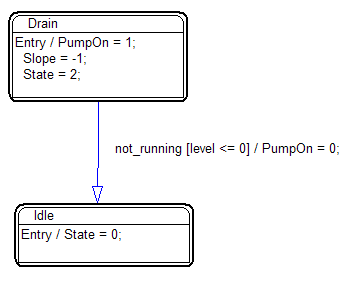
In the following example, a pump switches from draining mode to idle mode based on the transition specification:

The trigger not-running causes the pump to transition from ON to IDLE as long as the condition [level <=0] is TRUE.
To create a transition specification
1. Click the transition to highlight it in purple and right-click.
2. Right-click the transition and select Properties.
3. Under Edit Behavior, enter the transition specification.
4. Click OK to complete the transition behavior.
After you specify the transition specification, it appears on the transition in the state chart. You can drag the transition specification text to a new location. If you move the state or transition, the transition specification maintains its relative location on the transition.