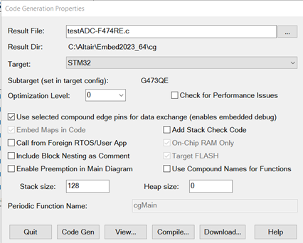
You can select one or more parameters in the Code Generation dialog to control how the code is generated.

Additional Compile Options: Lets you add additional compile options. See your compiler documentation for the options you can add. Specify the options in the format described in the compiler documentation.
Additional Linker Options: Lets you add additional linker options. See your linker documentation for the options you can add. Specify the options in the format described in the linker documentation.
Add Stack Check Code: Causes additional code to be generated that checks stack usage. The stack usage is reported with the Get Target Stack and Heap command.
Call from Foreign RTOS/User App: Lets you call the generated code from either a foreign RTOS on an embedded system or a user application.
Check for Performance Issues: Alerts you of operations that run slowly on an embedded system and advises how to change your diagram to improve performance. This parameter is available only for the devices that support it.
Embed Maps in Code: Builds the data files from any map block in the generated code. If the target does not have a file system, Embed automatically builds the data file in the generated code. If the target has a file system and you want to change the map file or if you want Embed to read the data file when the Embed application starts running, turn this parameter off. This parameter is available only for the devices that support it.
Enable Preemption in Main Diagram: Allows higher priority interrupts to preempt execution of the main diagram.
Heap Size: Allocates memory on the target. The heap is mainly used by matrix blocks and Embed housekeeping routines. Generally, 0x400 is sufficient for initialization of these routines.
To see how much heap is required in your target application, check the initMatVars() function in the generated C file. Each Mat Decl uses arg1 * arg2 * 4 bytes of heap. For a good estimate of heap usage, add all the bytes, plus an additional 500 bytes of Embed start-up heap. If your application has not allocated enough heap, Embed issues the following warning:
Insufficient memory to run on target
To correct this situation, increase the heap size and recompile.
This parameter does not apply to Arduino and Host targets; the heap is automatically allocated. Any value you enter is ignored.
Include Block Nesting as Comment: Includes comments in the generated code that indicate the source compound block from where the generated code came.
Inline Matrix Size Threshold: Specifies the threshold of a matrix to be generated as inline code. Matrices over the threshold are generated with function calls and for loops. Note that the computational savings of inline code generation goes down as a percent of the overall size of the matrix. In other words, the larger the matrix, the smaller the computational savings. The default is 0.
On-Chip RAM Only: Uses only on-chip RAM. This parameter is available only for devices with both on-chip and off-chip RAM.
Optimization Level: Specifies compiler optimization level, from 0 (no optimization) to 4 (highest level). In rare circumstances, Level 4 may yield inconsistent results, necessitating a lower level of optimization.
Periodic Function Name: Indicates the name of the main Embed time step function. This option can be ignored if you have not activated Call from Foreign RTOS/User App.
Result Dir: Displays where the result file will reside. Click … to select a different directory.
Result File: Indicates the C file to be created. By default, the name of the file is the name of the open block diagram. When you press Compile, Embed automatically creates the C file, then compiles and links it to create an OUT or ELF file. You can alternatively press Code Gen to create only a C file. Click Browse to browse the C file.
Stack Size: Allocates memory on the target device. The stack is used by function calls. Generally, 0x200 is adequate for most applications. This parameter is not available for Arduino and Host targets; the heap is automatically allocated. Any value you enter is ignored
Subtarget: Indicates the specific target device. The subtarget is set in the Target Config block in the diagram.
Target: Indicates the embedded device that the generated code runs on. Only the installed device libraries are in the drop-down list. To create a Windows DLL, select Host. To create a simulation object, you must first select a compound block, then select Simulation Object from the drop-down list.
Target FLASH: Most embedded targets have FLASH memory. This memory is read-only and will retain its information even after power is turned off.
When activated, Target FLASH causes the linker to allocate code and constants in FLASH and data in RAM. To write the resulting executable to FLASH on C2000 and ARM Cortex M3 devices, you use a third-party product, like Texas Instruments UniFlash. When Target FLASH is not activated, code and data are written to RAM.
For Arduino targets, code is automatically written to FLASH; you can ignore this parameter.
Use Compound Names for Functions: Instructs the code generator to use the compound block name instead of “system”+block ID” for the function generated if the compound block is enabled or has a special execution rate.
Use selected compound edge pins for data exchange: Enables HIL operation. The generated code running on the target sends and receives data from the block diagram running on the host.
This parameter is dimmed when no compound block is selected.