 Package Modelica.Fluid.Dissipation.Utilities.SharedDocumentation.HeatTransfer.StraightPipe
Icon for general information packages
Package Modelica.Fluid.Dissipation.Utilities.SharedDocumentation.HeatTransfer.StraightPipe
This icon indicates classes containing only documentation, intended for general description of, e.g., concepts and features of a package.
Extends from Modelica.Icons.Information (Icon for general information packages).
| Name | Description |
|---|---|
kc_laminar | |
kc_overall | |
kc_turbulent | |
kc_twoPhaseOverall |
 Class Modelica.Fluid.Dissipation.Utilities.SharedDocumentation.HeatTransfer.StraightPipe.kc_laminar
Calculation of mean convective heat transfer coefficient kc of a straight pipe at an uniform wall temperature or uniform heat flux and for a hydrodynamically developed or undeveloped laminar fluid flow.
There are basically three differences:
The mean convective heat transfer coefficient kc of a straight pipe in the laminar regime can be calculated for the following four heat transfer boundary conditions through its corresponding Nusselt number Nu :
Uniform wall temperature in developed fluid flow (heatTransferBoundary == Modelica.Fluid.Dissipation.Utilities.Types.HeatTransferBoundary.UWTuDFF) according to [VDI 2002, p. Ga 2, eq. 6] :
Nu_TD = [3.66^3 + 0.7^3 + {1.615*(Re*Pr*d_hyd/L)^1/3 - 0.7}^3]^1/3
Uniform heat flux in developed fluid flow (heatTransferBoundary == Modelica.Fluid.Dissipation.Utilities.Types.HeatTransferBoundary.UHFuDFF) according to [VDI 2002, p. Ga 4, eq. 19] :
Nu_qD = [4.364^3 + 0.6^3 + {1.953*(Re*Pr*d_hyd/L)^1/3 - 0.6}^3]^1/3
Uniform wall temperature in undeveloped fluid flow (heatTransferBoundary == Modelica.Fluid.Dissipation.Utilities.Types.HeatTransferBoundary.UWTuUFF) according to [VDI 2002, p. Ga 2, eq. 12] :
Nu_TU = [3.66^3 + 0.7^3 + {1.615*(Re*Pr*d_hyd/L)^1/3 - 0.7}^3 + {(2/[1+22*Pr])^1/6*(Re*Pr*d_hyd/L)^0.5}^3]^1/3
Uniform heat flux in developed fluid flow (heatTransferBoundary == Modelica.Fluid.Dissipation.Utilities.Types.HeatTransferBoundary.UHFuUFF) according to [VDI 2002, p. Ga 5, eq. 25] :
Nu_qU = [4.364^3 + 0.6^3 + {1.953*(Re*Pr*d_hyd/L)^1/3 - 0.6}^3 + {0.924*Pr^1/3*[Re*d_hyd/L]^0.5}^3]^1/3.
The corresponding mean convective heat transfer coefficient kc is determined w.r.t. the chosen heat transfer boundary by:
kc = Nu * lambda / d_hyd
with
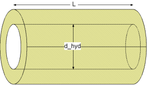
| d_hyd | as hydraulic diameter of straight pipe [m], |
| kc | as mean convective heat transfer coefficient [W/(m2K)], |
| lambda | as heat conductivity of fluid [W/(mK)], |
| L | as length of straight pipe [m], |
| Nu = kc*d_hyd/lambda | as mean Nusselt number [-], |
| Pr = eta*cp/lambda | as Prandtl number [-], |
| Re = rho*v*d_hyd/eta | as Reynolds number [-], |
| v | as mean velocity [m/s]. |
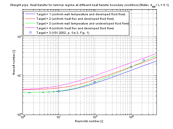
The mean Nusselt number Nu representing the mean convective heat transfer coefficient kc depending on four different heat transfer boundary conditions is shown in the figures below.
This verification has been done with the fluid properties of Water (Prandtl number Pr = 7) and a diameter to pipe length fraction of 0.1.
Extends from Modelica.Icons.Information (Icon for general information packages).
 Class Modelica.Fluid.Dissipation.Utilities.SharedDocumentation.HeatTransfer.StraightPipe.kc_overall
Calculation of mean convective heat transfer coefficient kc of a straight pipe at an uniform wall temperature or uniform heat flux and for a hydrodynamically developed or undeveloped laminar or turbulent fluid flow with neglect or consideration of pressure loss influence.
There are basically three differences:
This heat transfer function enables a calculation of heat transfer coefficient for laminar and turbulent flow regime. The geometry, constant and fluid parameters of the function are the same as for kc_laminar and kc_turbulent.
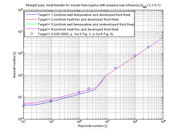
The calculation conditions for laminar and turbulent flow is equal to the calculation in kc_laminar and kc_turbulent. A smooth transition between both functions is carried out between 2200 ≤ Re ≤ 10000 (see figure below).
The mean Nusselt number Nu representing the mean convective heat transfer coefficient kc is shown for the fluid properties of Water (Prandtl number Pr = 7) and a diameter to pipe length fraction of 0.1 in the figure below.
The following verification considers pressure loss influence (roughness =2).
Extends from Modelica.Icons.Information (Icon for general information packages).
 Class Modelica.Fluid.Dissipation.Utilities.SharedDocumentation.HeatTransfer.StraightPipe.kc_turbulent
Calculation of mean convective heat transfer coefficient kc of a straight pipe for a hydrodynamically developed turbulent fluid flow at uniform wall temperature or uniform heat flux with neglecting or considering of pressure loss influence.
There are basically three differences:
Neglect pressure loss influence (roughness == 1):
The mean convective heat transfer coefficient kc for smooth straight pipes is calculated through its corresponding Nusselt number Nu according to [Dittus and Boelter in Bejan 2003, p. 424, eq. 5.76]
Nu = 0.023 * Re^(4/5) * Pr^(1/3).
Consider pressure loss influence (roughness == 2):
The mean convective heat transfer coefficient kc for rough straight pipes is calculated through its corresponding Nusselt number Nu according to [Gnielinski in VDI 2002, p. Ga 5, eq. 26]
Nu = (zeta/8)*Re*Pr/(1 + 12.7*(zeta/8)^0.5*(Pr^(2/3)-1))*(1+(d_hyd/L)^(2/3)),
where the influence of the pressure loss on the heat transfer calculation is considered through
zeta = (1.8*log10(Re)-1.5)^-2.
The mean convective heat transfer coefficient kc in dependence of the chosen calculation (neglecting or considering of pressure loss influence) results into:
kc = Nu * lambda / d_hyd
with
| d_hyd | as hydraulic diameter of straight pipe [m], |
| kc | as mean convective heat transfer coefficient [W/(m2K)], |
| lambda | as heat conductivity of fluid [W/(mK)], |
| L | as length of straight pipe [m], |
| Nu = kc*d_hyd/lambda | as mean Nusselt number [-], |
| Pr = eta*cp/lambda | as Prandtl number [-], |
| Re = rho*v*d_hyd/eta | as Reynolds number [-], |
| v | as mean velocity [m/s], |
| zeta | as pressure loss coefficient [-]. |
Note that there is no significant difference for the calculation of the mean Nusselt number Nu at a uniform wall temperature (UWT) or a uniform heat flux (UHF) as heat transfer boundary in the turbulent regime (Bejan 2003, p.303).
The mean Nusselt number Nu representing the mean convective heat transfer coefficient kc for Prandtl numbers of different fluids is shown in the figures below.
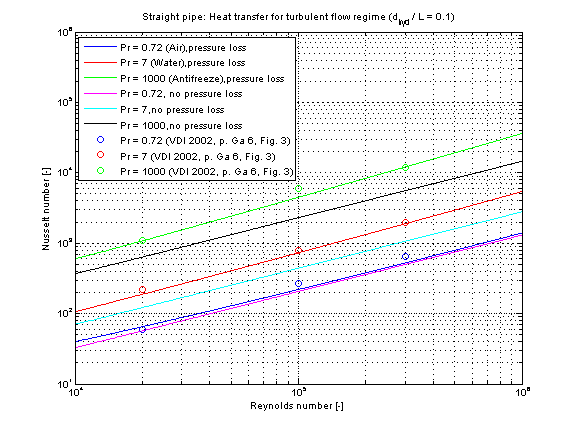
Note that the higher the Prandtl number Pr there is a higher difference in Nusselt numbers Nu comparing the neglect and consideration of pressure loss.
Extends from Modelica.Icons.Information (Icon for general information packages).
 Class Modelica.Fluid.Dissipation.Utilities.SharedDocumentation.HeatTransfer.StraightPipe.kc_twoPhaseOverall
Calculation of local two phase heat transfer coefficient kc_2ph for (horizontal/vertical) boiling or (horizontal) condensation for an overall flow regime.
Boiling in a horizontal pipe (target = Modelica.Fluid.Dissipation.Utilities.Types.TwoPhaseHeatTransferTarget.BoilHor):
The local two phase heat transfer coefficient kc_2ph during boiling in a horizontal straight pipe for an overall regime is calculated according to [Gungor/Winterton 1986, p.354, eq. 2] :
kc_2ph = E_fc*E_fc_hor*kc_fc+S_nb+S_nb_hor*kc_nb
with
| Bo=qdot_A/(mdot_A*dh_lv) | as boiling number [-], |
| dh_lv | as evaporation enthalpy [J/kg], |
| E_fc=f(Bo,Fr_l,X_tt) | as forced convection enhancement factor [-], |
| E_fc_hor =f(Fr_l) | as forced convection enhancement factor for horizontal straight pipes [-], |
| Fr_l | as Froude number assuming total mass flow rate flowing as liquid [-], |
| kc_2ph | as local two phase heat transfer coefficient [W/(m2K)], |
| kc_fc | as heat transfer coefficient considering forced convection [W/(m2K)], |
| kc_nb | as heat transfer coefficient considering nucleate boiling [W/(m2K)], |
| mdot_A | as total mass flow rate density [kg/(m2s)], |
| qdot_A | as heat flow rate density [W/m2], |
| Re_l | as Reynolds number assuming liquid mass flow rate flowing alone [-], |
| S_nb =f(E_fc,Re_l) | as suppression factor of nucleate boiling [-], |
| S_nb_hor =f(Fr_l) | as suppression factor of nucleate boiling for horizontal straight pipes [-], |
| x_flow | as mass flow rate quality [-], |
| X_tt = f(x_flow) | as Martinelli parameter [-]. |
Boiling in a vertical pipe (target = Modelica.Fluid.Dissipation.Utilities.Types.TwoPhaseHeatTransferTarget.BoilVer):
The local two phase heat transfer coefficient kc_2ph during boiling in a vertical straight pipe for an overall regime is calculated out of the correlations for boiling in a horizontal straight pipe, where the horizontal correction factors E_fc_hor,S_nb_hor are unity.
Please note that the correlations named above are not valid for subcooled boiling due to a different driving temperature for nucleate boiling and forced convection. At subcooled boiling there is no enhancement factor (no vapour generation) but the suppression factor remains effective.
Condensation in a horizontal pipe (target = Modelica.Fluid.Dissipation.Utilities.Types.TwoPhaseHeatTransferTarget.CondHor):
The local two phase heat transfer coefficient kc_2ph during condensation in a horizontal straight pipe for an overall regime is calculated according to [Shah 1979, p.548, eq. 8] :
kc_2ph = kc_1ph*[(1 - x_flow)^0.8 + 3.8*x_flow^0.76*(1 - x_flow)^0.04/p_red^0.38]
where the convective heat transfer coefficient kc_1ph assuming the total mass flow rate is flowing as liquid according to [Shah 1979, p.548, eq. 5] :
kc_1ph = 0.023*Re_l^0.8*Pr_l^0.4*lambda_l/d_hyd
with
| d_hyd | as hydraulic diameter [m], |
| kc_2ph | as local two phase heat transfer coefficient [W/(m2K)], |
| kc_1ph | as convective heat transfer coefficient assuming total mass flow rate is flowing as liquid [W/(m2K)], |
| lambda_l | as thermal conductivity of fluid [W/(mK)], |
| pressure | as thermodynamic pressure of fluid [Pa], |
| p_crit | as critical pressure of fluid [Pa], |
| p_red = pressure/p_crit | as reduced pressure [-], |
| Pr_l | as Prandtl number assuming [-], |
| Re_l | as Reynolds number assuming total mass flow rate is flowing as liquid [-], |
| x_flow | as mass flow rate quality [-], |
The local two phase heat transfer coefficient kc_2ph during for horizontal and vertical boiling as well as for horizontal condensation is shown for a straight pipe in the figures below.
Boiling in a horizontal pipe (target = Modelica.Fluid.Dissipation.Utilities.Types.TwoPhaseHeatTransferTarget.BoilVer):
Here the validation of the two phase heat transfer coefficient is shown for boiling in a horizontal straight pipe.
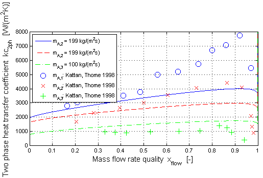
The two phase heat transfer coefficient (kc_2ph ) w.r.t. Gungor/Winterton is shown in dependence of the mass flow rate quality (x_flow ) for different mass flow rate densities (mdot_A ). The validation has been done with measurement results from Kattan/Thome for R134a as medium.
The two phase heat transfer coefficient increases with increasing mass flow rate quality up to a maximum value. After that there is a rapid decrease of (kc_2ph ) with increasing (x_flow ). This can be explained with a partial dryout of the pipe wall for a high mass flow rate quality.
Condensation in a horizontal pipe (target = Modelica.Fluid.Dissipation.Utilities.Types.TwoPhaseHeatTransferTarget.CondHor):
Here the validation of the two phase heat transfer coefficient is shown for condensation in a horizontal straight pipe.
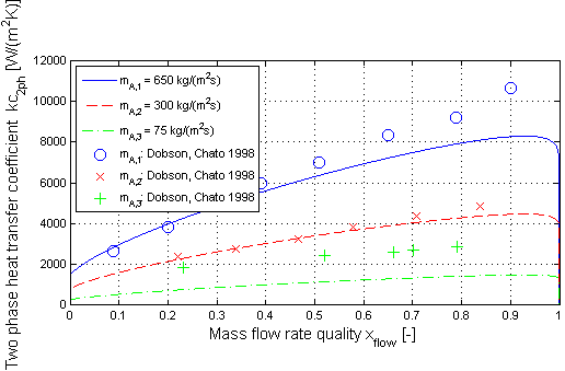
The two phase heat transfer coefficient (kc_2ph ) w.r.t. Shah is shown in dependence of the mass flow rate quality (x_flow ) for different mass flow rate densities (mdot_A ). The validation has been done with measurement results from Dobson/Chato for R134a as medium.
Extends from Modelica.Icons.Information (Icon for general information packages).