 Package HydraulicsByFluidon.Components.Lines
Icon for standard packages
Package HydraulicsByFluidon.Components.Lines
Standard package icon.
Extends from Modelica.Icons.Package (Icon for standard packages).
| Name | Description |
|---|---|
Base … | |
Bend | Bend |
Elbow | Elbow |
ExpansionContraction | Sudden Expansion / Contraction |
Hose | |
Pipe | |
PipeWithoutCapacity |
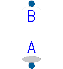 Model HydraulicsByFluidon.Components.Lines.PipeWithoutCapacity
Pipe model with resistive and inductive properties.
The pressure drop calculation is based on the assumption of quasi-steady friction. For turbulent flow through hydraulically rough pipes, the relative surface roughness (relRoughness) is taken into account. Geodetic pressure offset due to height differences between the pipe ports is considered in the simulation. The height difference deltaH is measured as the vertical distance between port B and port A of the pipe.
The calculated inductance depends on the flow regime (laminar or turbulent). The laminar inductance exceeds the turbulent one by a factor of 4/3.
If the parameter flowInitialization is activated, the initial mass flow rate will be calculated based on the potential difference between the two ports. If the check mark is not set, the initial flow rate will be zero even if a potential difference is present.
Please note: almost in every case it is necessary to add volumes at both ports.
Extends from HydraulicsByFluidon.Components.Base.HydTwoPortVertical.
| Type | Name | Default | Description |
|---|---|---|---|
Length | diameter | 0.032 | inner diameter |
Length | length | 1 | pipe length |
Length | deltaH | 0 | height difference |
DimensionlessRatio | relRoughness | 1e-6 | inner surface relative roughness |
Boolean | forwardFluidProperties | true | Forward fluid properties between ports |
| Type | Name | Description |
|---|---|---|
FluidPort | fluidPortA | Hydraulic port A |
FluidPort | fluidPortB | Hydraulic port B |
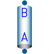 Model HydraulicsByFluidon.Components.Lines.Pipe
Pipe model with resistive, capacitive and inductive properties. Depending on pipe length, the Highest frequency to be covered and the Lowest speed of sound to be expected during the simulation, the pipe model is subdivided into several sub-pipes (inductive & resistive properties) and volumes (capacitive properties). Estimation of the required number of pipes is based on the following equation:
Irrespective of the parameterisation, at least two sub-pipes and one intermediate volume will be created. The total volume of the pipe is distributed equally over the individual volumes
The pressure drop calculation is based on the assumption of quasi-steady friction. For turbulent flow through hydraulically rough pipes, the relative surface roughness (relRoughness) is taken into account. Geodetic pressure offset due to height differences between the pipe ports is considered in the simulation. height difference between the ports B and A is measured as the vertical distance between port B and port A of the pipe.
The calculated inductance depends on the flow regime (laminar or turbulent). The laminar inductance exceeds the turbulent one by a factor of 4/3.
If the parameter Initialization of flow rate is activated, the mass flow rate will be initialized based on the potential difference between the two ports. If the check mark is not set, the initial flow rate will be zero even if a potential difference is present.
| Type | Name | Default | Description |
|---|---|---|---|
Length | diameter | 0.032 | inner diameter |
Length | length | 1 | pipe length |
Length | deltaH | 0 | height difference between the ports B and A |
DimensionlessRatio | relRoughness | 1e-6 | inner surface relative roughness |
Boolean | flowInitialisation | true | Initialization of flow rate |
Frequency | fMax | 10 | Highest frequency to be covered |
Velocity | cMin | 1000 | Lowest speed of sound to be expected |
Boolean | forwardFluidProperties | true | Forward fluid properties between ports |
TFluidPort | propertyPort | TFluidPort.portA | Property determining port if forwardFluidProperties = false |
| Type | Name | Description |
|---|---|---|
FluidPort | fluidPortA | Hydraulic port A |
FluidPort | fluidPortB | Hydraulic port B |
 Model HydraulicsByFluidon.Components.Lines.Hose
Hose model with resistive, capacitive and inductive properties. Depending on hose length, the Highest frequency to be covered and the Lowest speed of sound to be expected during the simulation, the hose model is subdivided into several sub-pipes (inductive & resistive properties) and volumes (capacitive properties). Estimation of the required number of pipes is based on the following equation:
Irrespective of the parameterisation, at least two sub-pipes and one intermediate volume will be created. The total volume of the hose is distributed equally over the individual volumes
The pressure drop calculation is based on the assumption of quasi-steady friction. For turbulent flow through hydraulically rough pipes, the relative surface roughness (relRoughness) is taken into account. Geodetic pressure offset due to height differences between the hose ports is considered in the simulation. height difference between the ports B and A is measured as the vertical distance between port B and port A of the hose.
The calculated inductance depends on the flow regime (laminar or turbulent). The laminar inductance exceeds the turbulent one by a factor of 4/3.
If the parameter Initialization of flow rate is activated, the mass flow rate will be initialized based on the potential difference between the two ports. If the check mark is not set, the initial flow rate will be zero even if a potential difference is present.
| Type | Name | Default | Description |
|---|---|---|---|
Length | diameter | 0.032 | Inner diameter |
Length | length | 1 | Hose length |
Length | deltaH | 0 | Height difference between the ports B and A |
DimensionlessRatio | relRoughness | 1e-6 | Inner surface relative roughness |
BulkModulus | bulkModulus | 1e+9 | Bulk modulus of hose |
Boolean | flowInitialisation | true | Initialization of flow rate |
Frequency | fMax | 10 | Highest frequency to be covered |
Velocity | cMin | 1000 | Lowest speed of sound to be expected |
Boolean | forwardFluidProperties | true | Forward fluid properties between ports |
TFluidPort | propertyPort | TFluidPort.portA | Property determining port if forwardFluidProperties = false |
| Type | Name | Description |
|---|---|---|
FluidPort | fluidPortA | Hydraulic port A |
FluidPort | fluidPortB | Hydraulic port B |
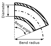
 Model HydraulicsByFluidon.Components.Lines.Bend
The component Bend is a valid model for Bend angle between 15° and 180°.
Please consider: The component was modeled in order to consider the pressure losses of well rounded bends. However, the use of the component can lead to extremely long simulation times, since a small stepsize must be selected due to the low resistance of an elbow.
Formulas are taken from W. Wagner, Strömung und Druckverlust, 7. Auflage 2012.
| Type | Name | Default | Description |
|---|---|---|---|
Length | Diameter | 0.032 | Diameter |
Angle | BendAngle | 0.5 * Modelica.Constants.pi | Bend angle |
Length | BendRadius | 0.1 | Bend radius |
DimensionlessRatio | relRoughness | 1e-6 | Relative roughness |
Volume | deadVolume | 1e-6 | Dead volume at ports |
Boolean | forwardFluidProperties | true | Forward fluid properties between ports |
Boolean | enableZetaOutput | false | Enable zeta output |
Boolean | enableReOutput | false | Enable Re output |
| Type | Name | Description |
|---|---|---|
FluidPort | fluidPortA | Hydraulic port A |
FluidPort | fluidPortB | Hydraulic port B |
output RealOutput | Zeta | Zeta |
output RealOutput | Re | Re |
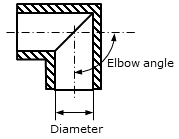
 Model HydraulicsByFluidon.Components.Lines.Elbow
The component Elbow is a valid model for Elbow angle between 30° and 120°.
Please consider: The component was modeled in order to consider the pressure losses of sharp edged elbows. However, the use of the component can lead to extremely long simulation times, since a small stepsize must be selected due to the low resistance of an elbow.
Formulas are taken from W. Wagner, Strömung und Druckverlust, 7. Auflage 2012, and Will, D., Hydraulik, Grundlagen, Komponenten, Schaltungen, 5. Auflage 2011.
| Type | Name | Default | Description |
|---|---|---|---|
Length | Diameter | 0.032 | Diameter |
Angle | Angle | 0.5 * Modelica.Constants.pi | Elbow angle |
Volume | deadVolume | 1e-6 | Dead volume at ports |
Boolean | forwardFluidProperties | true | Forward fluid properties between ports |
Boolean | enableZetaOutput | false | Enable zeta output |
Boolean | enableReOutput | false | Enable Re output |
| Type | Name | Description |
|---|---|---|
output RealOutput | Zeta | Zeta |
output RealOutput | Re | Re |
FluidPort | fluidPortA | Hydraulic port A |
FluidPort | fluidPortB | Hydraulic port B |
 Model HydraulicsByFluidon.Components.Lines.ExpansionContraction
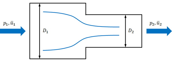
The component ExpansionContraction is a model of a cross section enlargement (diffusor) or a cross section reduction (nozzle). It depends on the flow direction.
The component computes the loss number zeta

according to the following equations:
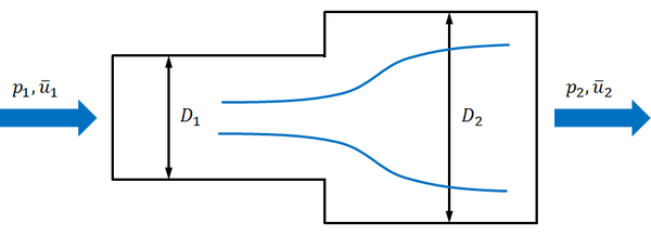
Borda-Carnot Equation


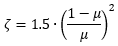
Formulas are taken from E. Truckenbrodt, Fluidmechanik, Band 1: Grundlagen und elementare Strömungsvorgänge dichtebeständiger Fluide, 4. Auflage, 2008.
Extends from HydraulicsByFluidon.Components.Base.HydTwoPortVerticalExt.
| Type | Name | Default | Description |
|---|---|---|---|
Length | D1 | 0.016 | Diameter 1 |
Length | D2 | 0.05 | Diameter 2 |
Volume | deadVolume | 1e-6 | Dead volume at ports |
Boolean | forwardFluidProperties | true | Forward fluid properties between ports |
| Type | Name | Description |
|---|---|---|
FluidPort | fluidPortA | Hydraulic port A |
FluidPort | fluidPortB | Hydraulic port B |