The user needs to configure the directions of observation
where the electrical far field is to be calculated. The user selects a combination of
angular sweeps in Theta or Phi, choosing in each case the number of samples for the
variable angular component and the number of cuts to be simulated between the initial
and final cuts, for the fixed angular value defined by the user. All the values for
Theta and Phi are entered in degrees.
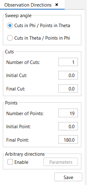
Figure 1. Observation Directions panel
The following settings are available:
Cuts in Phi / Points in Theta: the user selects to compute cuts in Phi and
angular sweeps in Theta.
Cuts in Theta / Points in Phi: the user selects to compute cuts in Theta and
angular sweeps in Phi.
Number of cuts: defines the number of samples in the angular cuts where the
user wants to compute the RCS.
Initial Cut: define the cut initial value (in degrees).
Final Cut: define the cut final value (in degrees).
Number of Points: defines the number of samples in the angular sweep where
the user wants to compute the RCS.
Initial Point: define the angular initial value (in degrees).
Final Point: define the angular final value (in degrees).
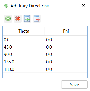
Additionally, the user can select Enable Arbitrary Directions and click on
Parameters button, then in the menu shown in Figure 2:
the user can import the information from a text file and show/edit the arbitrary
directions (theta/phi angles) where the RCS computation wants to be computed
the user can edit the arbitrary directions (theta/phi angles) where the RCS
computation wants to be computed and export them to a text file.
Figure 2. Arbitrary Directions panel
Note: Click Save before closing this window to confirm the
changes.