Parameters
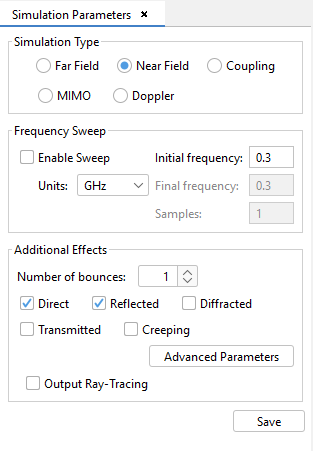
When the user selects this option, the following panel is shown:

In this panel, the user can set the main parameters of the simulation:
- Simulation Type
- There are five types of simulations:
- A far field simulation calculates the Far Field in the directions specified in the Output → Observation Directions option.
- A near field simulation calculates the Near Field of a set of points specified by the user, in the Output → Observation Points option.
- A coupling simulation calculates the coupling between two antennas. The user will have to introduce one or more active antennas and one passive antenna.
- A MIMO simulation calculates the same parameters as the coupling simulation, as well as the MIMO channel transfer matrix, the channel correlation and overall system capacity.
- A Doppler simulation calculates the Doppler shift. The user will have to introduce the Doppler parameters.
- Frequency Sweep
- To set the simulation frequency. The following parameters may be modified:
-
- Enable Sweep
- select this option to simulate a range of frequencies.
-
- Units
- to set the magnitude of the frequency. Hz, kHz, MHz and GHz are available.
-
- Initial frequency
- the first step in the frequency range, in the selected Units. If the frequency Sweep is disabled, this value coincides with the simulation frequency.
-
- Final frequency
- the last step in the frequency range, in the selected Units. This parameter may be only modified when the frequency Sweep is enabled.
-
- Samples
- number of frequency samples to be analyzed on the frequency Sweep. This parameter may be only modified when the frequency Sweep is enabled.
-
- Additional Effects
-
- Number of bounces: it is possible to define the number of interactions (bounces) to be taken into account in the simulation for each observation point.
- Direct: if this option is selected, the simulation will be performed taken into account direct rays.
- Reflected: if this option is selected, the simulation will be performed taken into account reflected rays.
- Diffracted: if this option is selected, the simulation will be performed taken into account diffraction.
- Creeping: if this option is selected, the simulation will be performed taken into account creeping waves.
- Transmission: if this option is selected, the simulation will be performed taken into account transmission.
- Output Ray-Tracing: if this option is selected, the .ray file will be generated in the simulation and the View Ray option in Show Results menu will be available.
- Selecting Advanced Parameters button, the following dialog will appear:

In this dialog the user can modify several advanced parameters of the simulation, most of them relative to the analysis of the creeping waves:
- Max. contributions: maximum number of contributions to taken into account. A contribution is for instance that due to a given double ray-path.
- Max. iterations: maximum number of contributions that are taken into account.
- Max. candidates: maximum number of surfaces that can shadow other surfaces.
- Max. Silhouette Points: maximum number of points for the silhouette when creeping wave paths are computed.
- Max. Geodesic Points: maximum number of geodesic points when computed a creeping wave path.
- Max Antenna facets: maximum number of facets to be stored in the anxel of Z-Buffer matrix of the antenna.
- Max Surface facets: maximum number of facets to be stored in the anxel of Z-Buffer matrix of every surface.
- Max Creeping Distance: maximum distance between a surface and the antenna to increase the creeping sample resolution.
- Creeping Square Size: size edge of the square where the creeping sample resolution is increased near the antenna.
- Creeping Higher Resolution: higher sampling resolution per surface used to compute the creeping silhouette.
- Creeping Lower Resolution: lower sampling resolution per surface used to compute the creeping silhouette.
After setting up the simulation parameters, press the Save button to save the configuration.