OS-V: 1020 Nelson-Mac Vaugh Rotor Model (3D Rotor)
The Nelson-Mac Vaugh rotor model for rotor dynamics is described to determine the
critical speeds at which resonance occurs. The Campbell diagram is used in to review
resonance and stability.
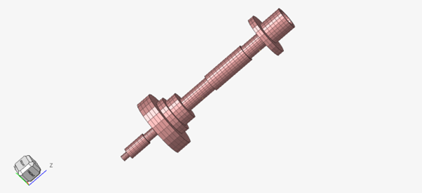
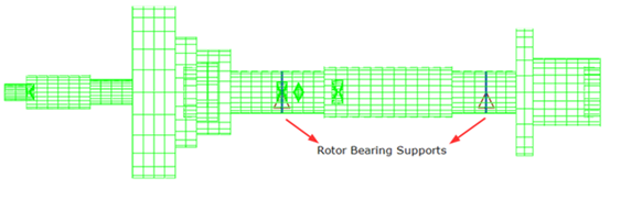
Figure 1. Model Figure 2. Rotor Bearing Supports
Model Files
Before you begin, copy the file(s) used in this problem
to your working directory.
Connected to support via RBE2 and
CELAS1 elements, damping is via
CDAMP1.
ASYNC Complex Eigenvalue Analysis with Gyroscopic effects.
Rotor speed increments via RSPEED from 0 to 100000 RPM,
in steps of 5000 RPM.
Material
The material properties are:
Property
Value
Young's modulus (E)
2.08E+11 N/m2
Poisson's Ratio (NU)
0.3
Mass Density (RHO)
7806 kg/m3
Results
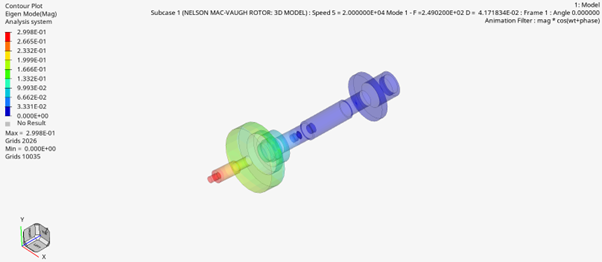
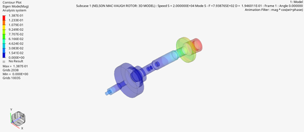
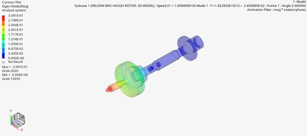
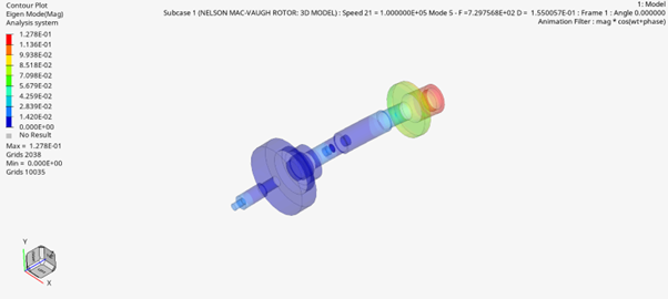
Table 1. Eigen Mode Contour Plots
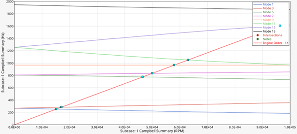
The Campbell diagram is one of the most crucial tools in rotor dynamic analysis
for comprehending the dynamic behaviour of the rotating machines. The rotational
speed (RPM) is plotted along the x-axis, while the frequency (Hz) is plotted along
the y-axis. To plot the Campbell diagram in HyperGraph,
import the Whirl modes, which are printed in the .out file. The
observation of the critical speeds comes from the Campbell diagram. Since the
analysis yields complex conjugate mode pairs, only alternate modes are plotted. The
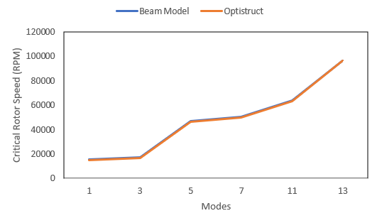
harmonic critical speeds can be observed at intersections at order = 1.0.Figure 3. OptiStruct Results