Coupling

Coupling refers to the forces and moments generated in a bushing to oppose the overall deformation of the bushing. These forces and moments are independent of any coordinate system that might be used to measure the deformation or deformation velocity. Coupling is an important factor when the bushing characteristics are non-linear.

Below is information on the formulation for coupling followed by three examples that show how coupling affects bushing force and torque output:

Coupling Formulation

The Altair Bushing Model supports three options for coupling:
  • Cylindrical coupling (2-dimensional)
  • Spherical coupling (3-dimensional)
  • No coupling

Two-dimensional coupling and three-dimensional coupling are analogous, and therefore, this guide explains coupling in terms of the two-dimensional concept.

For cylindrical coupling, assume:
  • A bushing has been fitted in two radial directions: x and y.
  • The internal states for the bushing are d, the bushing deformation, v, the bushing velocity, and q. These can change with direction.
  • Gx(d,v,q) defines the force function in the x-direction, as obtained by the fitting process.
  • Gy(d,v,q) defines the force function in the y-direction, as obtained by the fitting process.
  • During simulation, at any time t, the bushing undergoes deformations of (x, y) and deformation velocities of (˙x,˙y) .
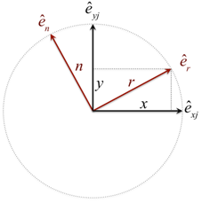
The diagram below shows the deformations and force vectors in the bushing. The J Marker is used as the coordinate system for all calculations.


Figure 1.
ˆexjandˆeyj
are the unit vectors along the x- and y-axes of the J marker. For cylindrical coupling, axial deformation is uncoupled. Only the x- and y-forces are coupled.
ˆer
is a unit vector along the deformation vector.
r
is the magnitude of the deformation. Its components along ˆexjandˆeyj are denoted as x and y respectively.
ˆen
is a unit vector orthogonal to the deformation vector. It points to the tangential velocity that may exist in the bushing.
The table below shows the various quantities of interest and how they are calculated:
Quantity Formula
Deforming vector r=rˆer=xˆexj+yˆeyj
Unit vector along radial deformation ˆer=(xr)ˆexj+(xr)ˆeyj
Unit vector perpendicular to deformation ˆen=(yr)ˆexj+(xr)ˆeyj
Bushing radial deformation r=r·r=(x2+y2)
Bushing tangential deformation r=r·ˆen=0
Deformation velocity vector ˙r=˙xˆexj+˙yˆeyj=vrˆer+vnˆen=(x·˙x+y·˙y)rˆer+(x·˙yy·˙x)rˆen
Bushing radial deformation velocity vr=(x·˙x+y·˙y)r
Bushing tangential deformation velocity vn=(x·˙yy·˙x)r
Bushing force vector F=Fxˆexj+Fyˆeyj=Frˆer+Fnˆen
Radial force Fr
Tangential force F n y r | y r | G x ( n , v n , q n x ) + x r | x r | G y ( r , v n , q n y ) = y r | y r | G x ( 0 , v n , q n x ) + x r | x r | G y ( 0 , v n , q n y ) MathType@MTEF@5@5@+= feaagKart1ev2aaatCvAUfeBSjuyZL2yd9gzLbvyNv2CaerbuLwBLn hiov2DGi1BTfMBaeXatLxBI9gBaerbd9wDYLwzYbItLDharqqtubsr 4rNCHbGeaGqiVu0Je9sqqrpepC0xbbL8F4rqqrFfpeea0xe9Lq=Jc9 vqaqpepm0xbba9pwe9Q8fs0=yqaqpepae9pg0FirpepeKkFr0xfr=x fr=xb9adbaqaaeGaciGaaiaabeqaamaabaabaaGceaqabeaacaWGgb WaaSbaaSqaaiaad6gaaeqaaOGaeSixIa0aaSaaaeaacaWG5baabaGa amOCaaaadaabdaqaamaalaaabaGaamyEaaqaaiaadkhaaaaacaGLhW UaayjcSdGaam4ramaaBaaaleaacaWG4baabeaakmaabmaabaGaamOB aiaacYcacaWG2bWaaSbaaSqaaiaad6gaaeqaaOGaaiilaiaadghada WgaaWcbaGaamOBaiaadIhaaeqaaaGccaGLOaGaayzkaaGaey4kaSYa aSaaaeaacaWG4baabaGaamOCaaaadaabdaqaamaalaaabaGaamiEaa qaaiaadkhaaaaacaGLhWUaayjcSdGaam4ramaaBaaaleaacaWG5baa beaakmaabmaabaGaamOCaiaacYcacaWG2bWaaSbaaSqaaiaad6gaae qaaOGaaiilaiaadghadaWgaaWcbaGaamOBaiaadMhaaeqaaaGccaGL OaGaayzkaaaabaGaaGjbVlaaysW7caaMe8UaaGjbVlabg2da9maala aabaGaamyEaaqaaiaadkhaaaWaaqWaaeaadaWcaaqaaiaadMhaaeaa caWGYbaaaaGaay5bSlaawIa7aiaadEeadaWgaaWcbaGaamiEaaqaba GcdaqadaqaaiaaicdacaGGSaGaamODamaaBaaaleaacaWGUbaabeaa kiaacYcacaWGXbWaaSbaaSqaaiaad6gacaWG4baabeaaaOGaayjkai aawMcaaiabgUcaRmaalaaabaGaamiEaaqaaiaadkhaaaWaaqWaaeaa daWcaaqaaiaadIhaaeaacaWGYbaaaaGaay5bSlaawIa7aiaadEeada WgaaWcbaGaamyEaaqabaGcdaqadaqaaiaaicdacaGGSaGaamODamaa BaaaleaacaWGUbaabeaakiaacYcacaWGXbWaaSbaaSqaaiaad6gaca WG5baabeaaaOGaayjkaiaawMcaaaaaaa@8AEC@
Force in the x-direction F x = F · e ^ x j = x r F r y r F n MathType@MTEF@5@5@+= feaagKart1ev2aaatCvAUfeBSjuyZL2yd9gzLbvyNv2CaerbuLwBLn hiov2DGi1BTfMBaeXatLxBI9gBaerbd9wDYLwzYbItLDharqqtubsr 4rNCHbGeaGqiVu0Je9sqqrpepC0xbbL8F4rqqrFfpeea0xe9Lq=Jc9 vqaqpepm0xbba9pwe9Q8fs0=yqaqpepae9pg0FirpepeKkFr0xfr=x fr=xb9adbaqaaeGaciGaaiaabeqaamaabaabaaGcbaGaamOramaaBa aaleaacaWG4baabeaakiabg2da9iqadAeagaWcaiabl+y6Njqadwga gaqcamaaBaaaleaacaWG4bGaamOAaaqabaGccqGH9aqpdaWcaaqaai aadIhaaeaacaWGYbaaaiaadAeadaWgaaWcbaGaamOCaaqabaGccqGH sisldaWcaaqaaiaadMhaaeaacaWGYbaaaiaadAeadaWgaaWcbaGaam OBaaqabaaaaa@4941@
Force in the y-direction F y = F · e ^ y j = y r F r + x r F n MathType@MTEF@5@5@+= feaagKart1ev2aaatCvAUfeBSjuyZL2yd9gzLbvyNv2CaerbuLwBLn hiov2DGi1BTfMBaeXatLxBI9gBaerbd9wDYLwzYbItLDharqqtubsr 4rNCHbGeaGqiVu0Je9sqqrpepC0xbbL8F4rqqrFfpeea0xe9Lq=Jc9 vqaqpepm0xbba9pwe9Q8fs0=yqaqpepae9pg0FirpepeKkFr0xfr=x fr=xb9adbaqaaeGaciGaaiaabeqaamaabaabaaGcbaGaamOramaaBa aaleaacaWG5baabeaakiabg2da9iqadAeagaWcaiabl+y6Njqadwga gaqcamaaBaaaleaacaWG5bGaamOAaaqabaGccqGH9aqpdaWcaaqaai aadMhaaeaacaWGYbaaaiaadAeadaWgaaWcbaGaamOCaaqabaGccqGH RaWkdaWcaaqaaiaadIhaaeaacaWGYbaaaiaadAeadaWgaaWcbaGaam OBaaqabaaaaa@4938@

Coupling Examples

Example 1: Isotropic Bushing with No Damping and Constant Rotating Deflection
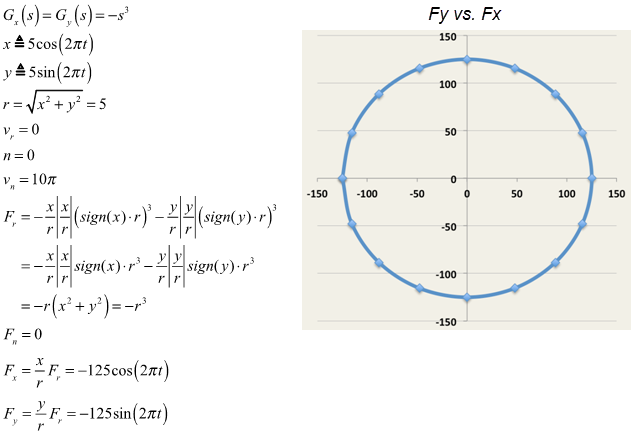
A constant deflection of 5 units stretching the bushing and rotating at 2*π radians/sec is imposed on the bushing. Rotation occurs in the X-Y plane of the J-Marker.

The following equations show the forces F x MathType@MTEF@5@5@+= feaagKart1ev2aaatCvAUfeBSjuyZL2yd9gzLbvyNv2CaerbuLwBLn hiov2DGi1BTfMBaeXatLxBI9gBaerbd9wDYLwzYbItLDharqqtubsr 4rNCHbGeaGqiVu0Je9sqqrpepC0xbbL8F4rqqrFfpeea0xe9Lq=Jc9 vqaqpepm0xbba9pwe9Q8fs0=yqaqpepae9pg0FirpepeKkFr0xfr=x fr=xb9adbaqaaeGaciGaaiaabeqaamaabaabaaGcbaGaamOramaaBa aaleaacaWG4baabeaaaaa@37EA@ and F y MathType@MTEF@5@5@+= feaagKart1ev2aaatCvAUfeBSjuyZL2yd9gzLbvyNv2CaerbuLwBLn hiov2DGi1BTfMBaeXatLxBI9gBaerbd9wDYLwzYbItLDharqqtubsr 4rNCHbGeaGqiVu0Je9sqqrpepC0xbbL8F4rqqrFfpeea0xe9Lq=Jc9 vqaqpepm0xbba9pwe9Q8fs0=yqaqpepae9pg0FirpepeKkFr0xfr=x fr=xb9adbaqaaeGaciGaaiaabeqaamaabaabaaGcbaGaamOramaaBa aaleaacaWG5baabeaaaaa@37EB@ computed by the coupling formulation. The plot shows that F y MathType@MTEF@5@5@+= feaagKart1ev2aaatCvAUfeBSjuyZL2yd9gzLbvyNv2CaerbuLwBLn hiov2DGi1BTfMBaeXatLxBI9gBaerbd9wDYLwzYbItLDharqqtubsr 4rNCHbGeaGqiVu0Je9sqqrpepC0xbbL8F4rqqrFfpeea0xe9Lq=Jc9 vqaqpepm0xbba9pwe9Q8fs0=yqaqpepae9pg0FirpepeKkFr0xfr=x fr=xb9adbaqaaeGaciGaaiaabeqaamaabaabaaGcbaGaamOramaaBa aaleaacaWG5baabeaaaaa@37EB@ vs. F x MathType@MTEF@5@5@+= feaagKart1ev2aaatCvAUfeBSjuyZL2yd9gzLbvyNv2CaerbuLwBLn hiov2DGi1BTfMBaeXatLxBI9gBaerbd9wDYLwzYbItLDharqqtubsr 4rNCHbGeaGqiVu0Je9sqqrpepC0xbbL8F4rqqrFfpeea0xe9Lq=Jc9 vqaqpepm0xbba9pwe9Q8fs0=yqaqpepae9pg0FirpepeKkFr0xfr=x fr=xb9adbaqaaeGaciGaaiaabeqaamaabaabaaGcbaGaamOramaaBa aaleaacaWG4baabeaaaaa@37EA@ is a circle as expected.


Figure 2.
Example 2: Isotropic Bushing with No Damping and Constant Rotating Force
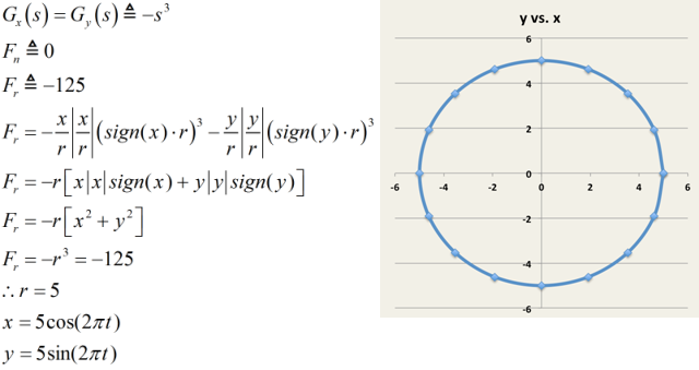
A constant tensile force of 125 units, rotating at 2*π radians/sec is imposed on the bushing. The force rotates in the X-Y plane of the J-Marker.

The following equations show the deformations x and y as computed by the coupling formulation. The plot shows y vs. x is a circle as expected.


Figure 3.
Example 3: Anisotropic Bushing with No Damping and Constant Rotating Force
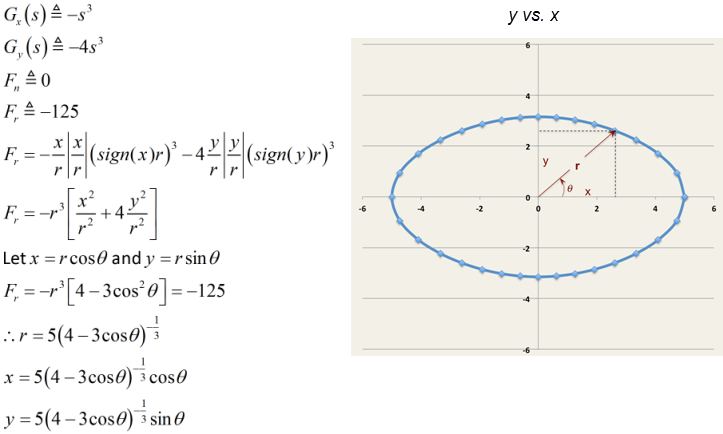
A constant tensile force of 125 units, rotating at 2*π radians/sec, is imposed on the bushing. Rotation occurs in the X-Y plane of the J-Marker.

The following equations show the deformations of x and y as computed by the coupling formulation. The plot shows that since the bushing is non-isotropic, the y vs. x plot is not a circle, but a smooth, elliptical, closed-curve as expected.


Figure 4.