OS-V: 1000 Complex Eigenvalue Analysis of Rotor Bearing System
Rotor Bearing system is an excellent example of rotating machines used in mechanical engineering applications.

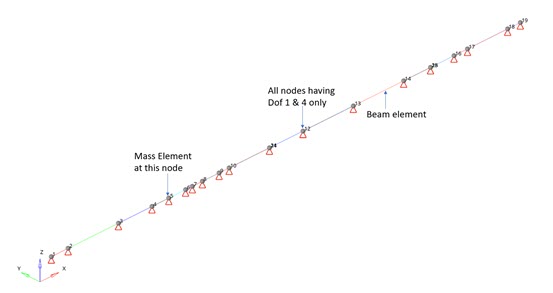
Figure 1. 1D Rotor Model

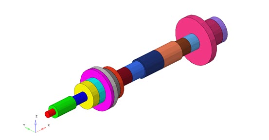
Figure 2. 3D Representation of Beams
Model Files
Benchmark Model
The finite element model, as shown in Figure 1 is constrained at all the nodes. Only DOF 1 and 4 are allowed on all the nodes. The model is meshed with beam elements of different sections (Figure 2). Mass is attached at node 5. An isotropic system is assumed.
Material
- Property
- Value
- Young's modulus
- 207.8 GN/m2
- Density
- 7806 kg/m3
- k22 = k33
- = 4.378 x e7 N/m
- k23 = k32
- = 0 N/m
- DMIG
- The stiffness matrix of the bearing is defined directly in the model as multiple column entries using K2GG.
- GENEL
- A file (.inc) which contains the details of bearing stiffness is imported in the model.
The problem has been solved for Complex Eigenvalue Analysis (ASYNC).
Results

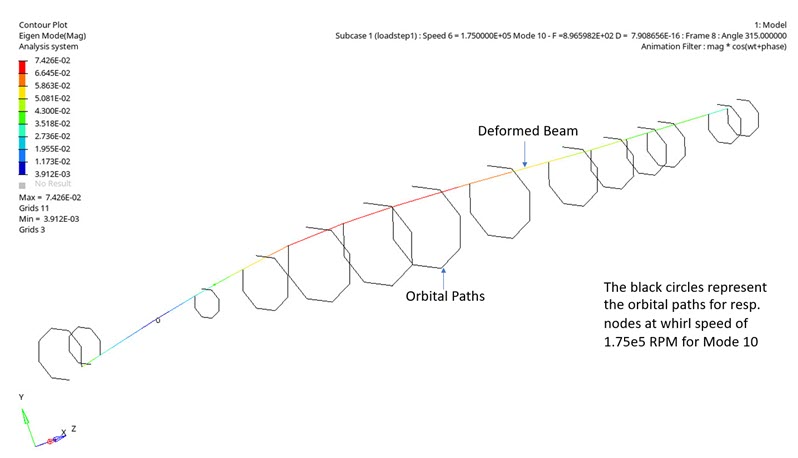
Figure 3. Eigen Mode Contour Plot for Spin Speed of 1.75e5 RPM and 10th Mode

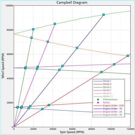
Figure 4. Campbell Diagram (For Engine Orders 0.5, 1, 2 and 4)
| Mode | Speed (RPM) | Normalized Value | |
|---|---|---|---|
| Nelson McVaugh 1 | OS 2 | ||
| 1 | 15470 | 15433.38 | 0.998 |
| 2 | 17159 | 17069.22 | 0.995 |
| 3 | 46612 | 46975.50 | 1.008 |
| 4 | 49983 | 50221.98 | 1.005 |
| 5 | 64752 | 65122.80 | 1.006 |
| 6 | 96547 | 92419.20 | 0.957 |
| Mode | Speed (RPM) | Normalized Value | |
|---|---|---|---|
| Nelson McVaugh 1 | OS 2 | ||
| 1 | 4015 | 4002.56 | 0.997 |
| 2 | 4120.20 | 4102.75 | 0.996 |
| 3 | 11989.25 | 12063.20 | 1.006 |
| 4 | 12200 | 12267.90 | 1.006 |
| 5 | 18184.25 | 18353.40 | 1.009 |
| 6 | 20162.25 | 20116.80 | 0.998 |
| Mode | Speed (RPM) | Normalized Value | |
|---|---|---|---|
| Nelson McVaugh 1 | OS 2 | ||
| 1 | 15858 | 15810.3 | 0.996992054 |
| 2 | 16700 | 16626.42 | 0.995594012 |
| 3 | 47520 | 47853 | 1.007007576 |
| 4 | 49204 | 49476.78 | 1.005482888 |
| 5 | 69640 | 70074 | 1.006232051 |
| 6 | 85552 | 84773.4 | 0.990899102 |
| Mode | Speed (RPM) | Normalized Value | |
|---|---|---|---|
| Nelson McVaugh 1 | OS 2 | ||
| 1 | 14758 | 14731.2 | 0.998184036 |
| 2 | 18148 | 18027.54 | 0.993362354 |
| 3 | 44695 | 45108.24 | 1.009245777 |
| 4 | 51430 | 51627.48 | 1.003839782 |
| 5 | 58424 | 58599.52 | 1.003004245 |
| 6 | 111455 | 101374.8 | 0.909558118 |
- Nomenclature
- Critical Speed
- The angular speed of a rotor that matches one of its natural frequencies.
- Whirl Ratio
- Ratio of whirl speed to spin speed.
- Campbell Diagram
- The plot of natural frequencies of the system as functions of the spin speeds.