HS-1630: Set Up an Optimization Based on a Flux Application Example

In this tutorial, you will complete an Optimization of a die press model to get a magnet with radial orientation.

Before you begin this tutorial:
  • Copy the Flux files used in this tutorial from <hst.zip>/HS-1630/ to your working directory.
  • Setup Flux to work with HyperStudy. For more information, refer to the registrations steps in Flux Model.

This tutorial is based on the example TEAM 25 dedicated on the optimization of a die press model.

The figure below shows an electromagnet with the die press in the center modeled with Flux 2D. The die molds are set to form a radial flux distribution in the cavity. The objective is to get specific induction Β MathType@MTEF@5@5@+= feaahqart1ev3aaatCvAUfeBSjuyZL2yd9gzLbvyNv2CaerbuLwBLn hiov2DGi1BTfMBaeXatLxBI9gBaerbd9wDYLwzYbItLDharqqtubsr 4rNCHbGeaGqiVu0Je9sqqrpepC0xbbL8F4rqqrFfpeea0xe9Lq=Jc9 vqaqpepm0xbba9pwe9Q8fs0=yqaqpepae9pg0FirpepeKkFr0xfr=x fr=xb9adbaqaaeGaciGaaiaabeqaamaabaabaaGcbaWaa8Haaeaacq qHsoGqaiaawEniaaaa@3909@ on the magnet inserted in the cavity: Β x MathType@MTEF@5@5@+= feaahqart1ev3aaatCvAUfeBSjuyZL2yd9gzLbvyNv2CaerbuLwBLn hiov2DGi1BTfMBaeXatLxBI9gBaerbd9wDYLwzYbItLDharqqtubsr 4rNCHbGeaGqiVu0Je9sqqrpepC0xbbL8F4rqqrFfpeea0xe9Lq=Jc9 vqaqpepm0xbba9pwe9Q8fs0=yqaqpepae9pg0FirpepeKkFr0xfr=x fr=xb9adbaqaaeGaciGaaiaabeqaamaabaabaaGcbaGaeuOKdiKaam iEaaaa@3852@ and Β y MathType@MTEF@5@5@+= feaahqart1ev3aaatCvAUfeBSjuyZL2yd9gzLbvyNv2CaerbuLwBLn hiov2DGi1BTfMBaeXatLxBI9gBaerbd9wDYLwzYbItLDharqqtubsr 4rNCHbGeaGqiVu0Je9sqqrpepC0xbbL8F4rqqrFfpeea0xe9Lq=Jc9 vqaqpepm0xbba9pwe9Q8fs0=yqaqpepae9pg0FirpepeKkFr0xfr=x fr=xb9adbaqaaeGaciGaaiaabeqaamaabaabaaGcbaGaeuOKdiKaam yEaaaa@3853@ along the computation path should fit the reference shown in the figure below. The table below shows the eight designs with their ranges of variation.


Figure 1.
Table 1.
Parameter Initial (mm) Min (mm) Max (mm)
R1 7.2 5 9.4
L2 15.3 12.6 18
L3 14 14 45
L4 11.5 4 19
AUX1 180 170 190
AUX2 80 70 90
AUX3 88 86 90
AUX4 9.5 9.5 11


Figure 2.
Best practice to solve this kind of an optimization problem is to minimize the integral of the summed squared differences between the computed and the reference values at each point. The objective function is defined in the equation below, where n is the number of points on the computation path.(1) F = i = 1 n ( Β x Β x _ r e f ) 2 + ( Β y Β y _ r e f ) 2 MathType@MTEF@5@5@+= feaahqart1ev3aaatCvAUfeBSjuyZL2yd9gzLbvyNv2CaerbuLwBLn hiov2DGi1BTfMBaeXatLxBI9gBaerbd9wDYLwzYbItLDharqqtubsr 4rNCHbGeaGqiVu0Je9sqqrpepC0xbbL8F4rqqrFfpeea0xe9Lq=Jc9 vqaqpepm0xbba9pwe9Q8fs0=yqaqpepae9pg0FirpepeKkFr0xfr=x fr=xb9adbaqaaeGaciGaaiaabeqaamaabaabaaGcbaGaamOraiabg2 da9maaqahabaWaamWaaeaacaGGOaGaeuOKdiKaamiEaiabgkHiTiab fk5acjaadIhacaGGFbGaamOCaiaadwgacaWGMbGaaiykamaaCaaale qabaGaaGOmaaaakiabgUcaRiaacIcacqqHsoGqcaWG5bGaeyOeI0Ia euOKdiKaamyEaiaac+facaWGYbGaamyzaiaadAgacaGGPaWaaWbaaS qabeaacaaIYaaaaaGccaGLBbGaayzxaaaaleaacaWGPbGaeyypa0Ja aGymaaqaaiaad6gaa0GaeyyeIuoaaaa@57CA@

Perform Study Setup

In this step, you will setup the study.

The design variables and the responses are created in Flux and are exported to HyperStudy through a link file.

  1. Start HyperStudy.
  2. Start a new study in the following ways:
    • From the menu bar, click File > New.
    • On the ribbon, click .
  3. In the Add Study dialog, enter a study name, select a location for the study, and click OK.
    Tip: It is recommended to save the study in the same location as the Flux files.
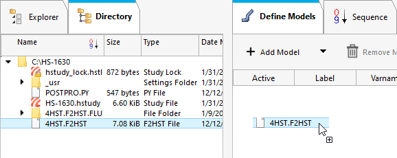
  4. Go to the Define Models step.
    1. From the Directory, drag and drop the 4HST.F2HST file into the work area.


      Figure 3.
    2. Click Import Variables.
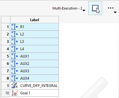
    HyperStudy creates a Flux model, imports eight input variables and one response from the Flux file, and populates the Solver Execution Script and Solver Input Arguments tabs.
  5. Go to the Define Input Variables step.
    1. Modify the lower and upper bound ranges as seen in the table below.
      Table 2.
      Label New Lower Bound New Upper Bound
      R1 5 9.4
      L2 12.6 18
      L3 14 45
      L4 4 19
      AUX1 170 190
      AUX2 70 90
      AUX3 86 90
      AUX4 9.5 11
  6. Go to the Test Models step.
    1. Click Run Definition.
  7. Go to the Define Output Responses step.
    1. Click the Objectives/Constraints - Goals tab and select Add Goal.
    2. Verify the goal is applied on Curve_DIFF_INTEGRAL (r_1) and the type is set to Minimize.


      Figure 4.
    3. Click Evaluate.

    An approach/nom_1/ directory is created inside the study directory. The directory contains the run__00001/m_1 directory where the solved Flux files are stored.

Run Optimization Using GRSM

In this step, you will add and run an Optimization using the Global Response Search Method (GRSM) method.

  1. Add an Optimization.
    1. In the Explorer, right-click and select Add from the context menu.
    2. In the Add dialog, select Optimization and enter GRSM for the label.
    3. For Definition from, select an approach.
    4. Click OK.
  2. Go to the Specifications step.
    1. In the work area, select the Global Response Search Method (GRSM) method.
    2. Keep the default settings.
    3. Click Apply.
  3. Go to the Evaluate step.
    1. Click Evaluate Tasks.
      Tip: You can supervise the Optimization progress and final results in the Iteration History and Iteration Plot tabs. The optimum solution is highlighted green in the table.
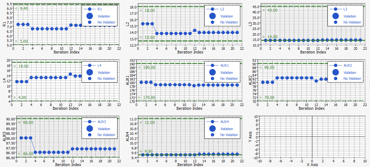
  4. Optional: Display the plots of the dvs variations vs the iterations.
    1. Go to the Iteration Plot tab.
    2. From the Channel Selector, display the plots for R1 through AUX4.
    3. Select Multiplot.


      Figure 5.
    4. Click Options, and select Bounds from the drop-down menu.
    5. Right-click on one of the plots, and select All > Legend from the context menu.
    6. Analyze the plots to determine if the allowed bounds have been reached. As indicated in the figure below, only the L3 min bound is reached.


    Figure 6.

Run Optimization Using GRSM with Inclusion Matrix

In this step, you will run a second Optimization using the Global Response Search Method (GRSM) method with Inclusion Matrix to see if a better solution can be found.

The second GRSM will start from the optimum solution found in the first Optimization ran in Run Optimization Using GRSM. The evaluations from the first Optimization using GRSM are imported as an Inclusion Matrix and 50 new runs are completed.

  1. From the Explorer, right-click on the GRSM Optimization approach and select Copy from the context menu.
  2. In the Copy dialog, enter GRSM_InclMatrix for the label and click OK.
  3. Go to theGRSM InclMatrix > Specifications step.
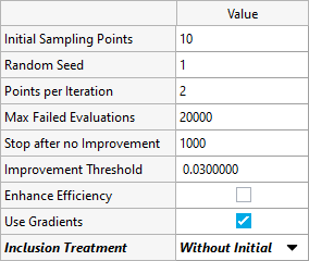
    1. From the Channel selector, click the More tab.
    2. For Use Inclusion Treatment, select Without Initial from the drop-down menu to enable Use Inclusion Matrix.


      Figure 7.
    3. In the Matrix area, click Edit in the Display column.


      Figure 8.
    4. In the Edit Inclusion Matrix dialog, click Import Values.
    5. In the table, select Approach evaluation data and then click Next.
    6. Select GRSM (opt_1) from the drop-down menu and then click Next.
    7. Click Finish and then click OK.
    8. Click Apply to validate the specifications.
  4. Go to the Evaluate step.
    1. Click Evaluate Tasks.

      You will see 50 runs included from the first GRSM. The included runs are used to perform the first iteration of the second GRSM optimization. As a result, the best solution in Iteration one is the optimum solution obtained with the first GRSM.

Results Overview

Review the results of the tutorial.
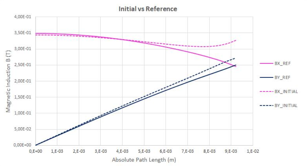


Figure 9.


Figure 10.