Glossary
- Absorption Coefficient
- The sound-absorption coefficient for an absorbing surface of infinite extent. It is the ratio of sound energy absorbed by the surface to the sound energy incident upon the surface when the incident sound field is perfectly diffuse.
- Acoustic
- An element type supporting acoustic modes, such as axial (one-dimensional), tangential (two-dimensional), or oblique (three dimensional) modes.
- Beam
- A one-dimensional structural element with a constant cross-section supporting bending, torsional, longitudinal, and higher-order cross-sectional deformation modes.
- Bending
- A motion in which the deflection is transverse to the plane of the structure.
- Compliance
- Compliance is a subsystem output derived quantity. The compliance, Cd of an acoustic subsystem is the ratio of total energy (twice the potential energy) to the average mean-square pressure.
- Compression
- A motion in which the deflection is normal to the cross-section of the structure and causes a compressional (inward) stress on the material.
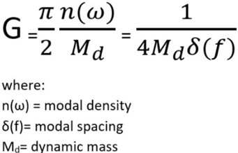
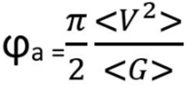
- Conductance
- The point conductance for a structural subsystem is the real part of the
drive-point mobility (velocity/force). Conductance can be measured,
estimated from finite element models, or calculated analytically. For
SEA calculations, the conductance is calculated from:
(1) 
- Connections
- Used to define the way in which elements of the model are connected together, connections provide paths for vibration and acoustic power flow between elements and establish degrees-of-freedom at the element interfaces. A single connection contains one or more SEA junctions.
- Coupling Factor
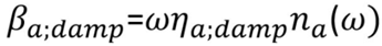
- In SEAM, the ratio of subsystem energy to modal density is called the "modal power". The power flow between coupled subsystems can be written in terms of the difference in modal powers and a coupling factor:
-
(2) 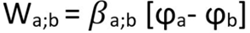
-
(3) 
-
(4) 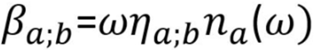
-
(5) 
- The use of modal power and coupling factors to derive the SEA power
balance equations offers several advantages over the conventional SEA
derivation.
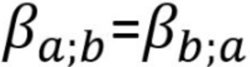
- For many types of junctions the coupling factor can be determined more directly than the coupling loss factor. The coupling factor is closely related to the power transmission coefficient - a parameter that can be measured using acoustic and/or structural intensity probes or a transmission loss facility.
- Unlike the coupling loss factor, the coupling factor is reciprocal:
(6) 
- Modal power and coupling factors can be defined for a band of frequencies or for a single frequency. This allows SEA to be used to study both broadband random and periodic excitations, which are commonly encountered for rotating machinery. A conventional SEA formulation requires that an effective bandwidth be defined for the single-frequency excitation components.
- The modal power can be measured, since it can be defined in
terms of the average response velocity and the average
drive-point conductance of the subsystem:
(7) 
where is the mean-square velocity averaged over frequency and over locations on the subsystem and is the drive-point conductance (real part of the mobility) averaged over frequency and drive-point locations within the subsystem. Both the average mean-square velocity and the average drive-point conductance can be obtained from measured data, thereby providing a measurement of the modal power. The conventional SEA derivation requires modal energy and mode count, which are more difficult to measure. Measurement of modal energy is more difficult, since it is difficult to measure energy for non-homogeneous structures. Measurement of the mode count is also difficult due to the large number of modes at high frequencies.
- Cross Coupling
- Cross-coupling couples the bending and inplane subsystems within a structural element. This coupling is caused physically by interactions between the rotational and translational degrees-of-freedom at element boundaries and discontinuities.
- Damping
- The dissipation of energy within a structural subsystem as the structure deforms or within an acoustic subsystem as the acoustical energy is attenuated in the medium or dissipated by absorptive surfaces.
- Damping Loss Factor
- The ratio of the energy dissipated per radian to the maximum potential energy. The damping loss factor is commonly denoted by the symbol η. In SEA, the loss factors at system resonances are used, in which case the loss factor is equal to twice the critical damping ratio, η = 2ζ.
- Density
- It is the weight (English units) or mass (Metric units) per unit volume of a material. The density is commonly denoted by the symbol ρ.
- Derived Quantities
- The derived quantities are output results determined by the SEA analysis code. Derived quantities are provided for each SEA subsystem. The results include: modal spacing, modal density, conductance, resistance, dynamic mass, compliance, wavelength, wave number, loss factor, and modal overlap.
- Duct
- An acoustic element with a large aspect ratio capable of supporting one dimensional (axial) acoustic modes. An acoustic duct element can also support two and three dimensional acoustic modes at higher frequencies.
- Dynamic Mass
- The dynamic mass is defined as the ratio of total energy (twice the kinetic energy) to average mean-square velocity. This value is normally equivalent to the total mass of the subsystem, a product of density and volume.
- Element
- Used to define a substructure or acoustic region, elements store and dissipate vibratory energy and provide paths for vibration and acoustic power flow. A single element contains one or more SEA subsystems.
- Excitation
- An excitation is generated from an input load. An excitation acts on an SEA subsystem or junction, whereas an input load acts on a SEAM element or connection.
- Function
- A frequency-dependent curve or array of values. Functions are used to describe frequency dependent damping, stiffness, conductance, and other properties as well as excitations. Functions were called Tables in previous versions of SEAM.
- Group
- A group of elements, connections, and/or input loads. Groups are useful in SEA NET and in sorting tabular model data.
- Honeycomb Panel
- A layered plate consisting of a honeycomb core sandwiched between two face sheets.
- Impedance
- Impedance is calculated by SEAM and reported as a derived quantity.
- Inplane
- A general term encompassing modes in which the deflection is in the plane of the structure. Inplane modes include compression and some types of shear.
- Input Load
- Power input to the model from vibration and acoustic sources.
- Junction
- An SEA junction is an energy flow path between two or more SEA subsystems corresponding to a single degree of freedom
- Junction Impedance
- Junction impedance is calculated by SEAM and reported as a derived quantity. The junction impedance is the sum of all subsystem impedances connected at the junction. The junction impedance is used to adjust coupling between the subsystems. If a mass is present at the junction, the mass impedance is added to the total junction impedance. If an isolating spring is present, the impedance of the isolated subsystem is adjusted according to the spring impedance.
- Junction Perimeter
- The junction perimeter is a term which modifies the radiation coupling determined from a structural acoustic area connection. The radiation perimeter is the length of large impedance discontinuities on the structural element. Radiation from these discontinuities can be important at low frequencies. In general, the junction perimeter should be set equal to the structural element discontinuities (the length of clamped edges and heavy ribs).
- Layer
- A thin acoustic element of large extent, which is capable of supporting two dimensional (tangential) acoustic modes. An acoustic layer element can also support three dimensional acoustic modes at higher frequencies.
- Longitudinal Wave Speed
- The Longitudinal Wave Speed is also called the Dilitational or the Irrotational Wave Speed and is commonly denoted by cL. The definition of the longitudinal wave speed is different for one two and three dimensional structures.
- The longitudinal wave speed in a beam:
(8) 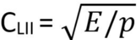
- The longitudinal wave speed in a plate is:
(9) 
- The longitudinal wave speed in a solid is:
(10) 
- Loss Factor
- Loss factor is a subsystem output derived quantity. It is defined as the ratio of energy dissipated per unit time to average energy stored by the subsystem.
- Material
- A collection of properties which define the density and wave speed of a single material.
- Modal Density
- Modal density is a subsystem output derived quantity. It is defined as the ratio of the number of resonant modes in a frequency band to the frequency bandwidth.
- Modal Energy
- Modal energy is a subsystem output response. It is defined as the ratio of the effective damping bandwidth of a mode to the average spacing between modes.
- Modal Overlap
- Modal overlap is a subsystem output derived quantity. It is defined as the ratio of the number of resonant modes in a frequency band to the frequency bandwidth.
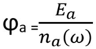
- Modal Power
- Modal power is a subsystem output response. It is defined as the ratio of the subsystem total energy to the modal density.
-
(11)
-
(12)
-
(13)
- The use of modal power and coupling factors to derive the SEA power
balance equations offers several advantages over the conventional SEA
derivation.
- For many types of junctions the coupling factor can be determined more directly than the coupling loss factor. The coupling factor is closely related to the power transmission coefficient - a parameter that can be measured using acoustic and/or structural intensity probes or a transmission loss facility.
- Unlike the coupling loss factor, the coupling factor is
reciprocal:
(14)
- Modal power and coupling factors can be defined for a band of frequencies or for a single frequency. This allows SEA to be used to study both broadband random and periodic excitations, which are commonly encountered for rotating machinery. A conventional SEA formulation requires that an effective bandwidth be defined for the single-frequency excitation components.
- The modal power can be measured, since it can be defined in
terms of the average response velocity and the average
drive-point conductance of the subsystem:
(15)
where is the mean-square velocity averaged over frequency and over locations on the subsystem and is the drive-point conductance (real part of the mobility) averaged over frequency and drive-point locations within the subsystem. Both the average mean-square velocity and the average drive-point conductance can be obtained from measured data, thereby providing a measurement of the modal power. The conventional SEA derivation requires modal energy and mode count, which are more difficult to measure. Measurement of modal energy is more difficult, since it is difficult to measure energy for non-homogeneous structures. Measurement of the mode count is also difficult due to the large number of modes at high frequencies.
- Modal Spacing
- Modal spacing is a subsystem output derived quantity. It is defined as the average frequency separation between resonant modes of a subsystem. Small values of mode spacing indicate that many subsystem modes are present in the current frequency band.
- Noise Reduction
- Noise reduction is a subsystem output calculated quantity. It is defined as the difference in pressure between two acoustic spaces. The noise reduction is always provided in dB units. The calculation of noise reduction depends on whether the acoustic response is given in dB or linear units.
- Non-structural Mass
- Additional mass attached to a structure which does not alter its stiffness properties.
- Response, Peak
- The peak responses are determined from output results of the SEA analysis code. When the standard deviation in the analysis band is calculated, peak responses are found by adding twice the subsystem standard deviation to the average response of each subsystem. The results include peak acceleration, velocity, or displacement for structures and pressure for acoustic volumes.
- Plate
- A two-dimensional flat panel structural element supporting bending and inplane deformation modes.
- Poisson's Ratio
- For an elastic material strained by a force in one direction, Poisson's Ratio is the ratio of the corresponding strain in a direction perpendicular to the initial strain. Poisson's ratio is commonly denoted by the symbol ν. It is related to Young's Modulus and the Shear Modulus by the following equation: (1+ν) = E/2G.
- Power Spectral Density (PSD)
- SEA vibration or pressure predictions may be reported as a power spectral density (PSD) by normalizing by the analysis bandwidth. Altair Seam post-processes the SEAM output to generate plots and tables of the mean vibration or pressure PSD. If the acceleration reference for the analysis is set to 1 G (i.e. 386 in/sec), acceleration PSD will be reported as G^2/Hz.
- Property
- Element cross-section and material properties may be defined using property records. The use of property records is optional since element properties can be entered directly for each Altair Seam element on the element parameter definition form. However, use of a property record will simplify the SEA model development when many different elements share the same cross-section and materials. Examples include hull and piping elements in ships, shell elements in aircraft and launch vehicles, and walls of buildings and enclosures.
- Record
- A record contains all the information required to define a single element, connection, material, Input Load, damping or table. A record is contained in a single definition form, or in a single line in a list spreadsheet.
- Response
- The Responses are output results determined by the SEA analysis code. Responses are provided for each SEA subsystem. The results include: modal power, modal energy, total energy, acceleration/velocity /displacement/pressure response, and standard deviation.
- Response, Peak Resistance
- Resistance is a subsystem output derived quantity. It is defined as the real part of the acoustic impedance (pressure/volume velocity).
- Reverberation Time
- Reverberation time is a method used to determine the energy dissipation of acoustic elements. The reverberation time is defined as the time in seconds required for sound pressure at a specific frequency to decay 60 dB after the sound source is stopped.
- SEANET
- SEANET is a graphical network view of the model that uses icons and connection lines to represent the elements, input loads, and connections in a SEAM model.
- Shear
- A motion in which the deflection is tangential to a section or surface of the structure causing two contiguous parts of the structure to slide relative to each other along their plane of contact. Shear modes can deflect in a direction that is lateral (inplane) or transverse to the plane of the structure.
- Shear Modulus
- The ratio of the shear stress divided by the shear strain. The Shear Modulus is also called the Modulus of Rigidity and is commonly denoted by the letter G.
- Sheer Wave Speed
- The Shear Wave Speed also called the Distortional, Transverse, or Rotational Wave Speed and is commonly denoted by cs. The shear wave speed is defined by:
-
(16) 
- Shell
- A two-dimensional structural element supporting radial, tangential, and longitudinal deformation modes.
- Space
- A large, three dimensional acoustic element, which is only capable of supporting three dimensional (oblique) acoustic modes.
- Speed of Sound
- The speed at which sound waves travel through an acoustic medium, such as a liquid or a gas. The Speed of Sound is also called the Acoustic Wave Speed and is commonly denoted by the letter c.
- Standard Deviation
- Standard deviation is a subsystem output response. It is useful in enveloping the peaks in the response of a subsystem by adding two times the standard deviation to the subsystem response in dB.
- Structural
- An element supporting structural modes, such as bending, shear, or torsion.
- Subsystem
- An SEA subsystem is a group of modes with similar characteristics, such as resonant frequency, mode shape, damping, and coupling.
- Symbol
- A user-defined constant which is defined by a name, quantity, value, and system of units. Symbols are used to represent common dimensions and parameters of a model. Defining a model using symbols allows you to make quick changes to a model.
- Table
- A frequency dependent array of values. Tables are called Functions in more recent versions of SEAM.
- Torsion
- One-dimensional shear motion in which the cross-section of a structure exhibits twisting.
- Total Energy
- Total energy is a subsystem output response. It is defined as twice the potential energy or twice the kinetic energy of a subsystem.
- Transfer Function
- Transfer function is a subsystem output calculated quantity. It is defined as the difference or ratio of subsystem responses. The transfer function is always provided in dB units. The calculation of transfer function depends on whether the responses are given in dB or linear units.
- Transmission Loss
- The difference between incident sound intensity level and transmitted sound intensity level. Transmission loss is in decibels, and is related to the transmission coefficient, τ, by: TL = 10 log (1/τ)
- Vibration Reduction
- Vibration reduction is a subsystem output calculated quantity. It is defined as the difference in acceleration between two structural elements. The vibration reduction is always provided in dB units. The calculation of vibration reduction depends on whether acceleration response is given in dB or linear units.
- Wavelength
- Wavelength is a subsystem output derived quantity. It is defined as the average distance between wave crests in a traveling wave, which are separated by one period.
- Wave Number
- Wave number is a subsystem output derived quantity. It is defined as the ratio of two times π divided by wavelength
- Young's Modulus
- The ratio of stress (force per unit area) to strain (deformation per unit length) for any material. Young's Modulus is expressed in units of stress. Young's Modulus is also call the Modulus of Elasticity and is commonly denoted by the letter E.