Browsers provide a structured view of model data, which you can use to review, modify, create, and manage
the contents of a model. In addition to visualization, browsers offer features like search, filtering, and sorting,
which enhance your ability to navigate and interact with the model data.
FE geometry is topology on top of mesh, meaning CAD and mesh exist as a single entity. The purpose of FE geometry
is to add vertices, edges, surfaces, and solids on FE models which have no CAD geometry.
Tools and workflows that are dedicated to rapidly creating new parts for specific use cases, or amending existing
parts. The current capabilities are focused on stiffening parts.
Use PhysicsAI to build fast predictive models from CAE data. PhysicsAI can be trained on data with any physics or
remeshing and without design variables.
A multibody system study generally involves the following broad steps. The following sections give a brief introduction
on using MotionView and the related products to conduct such a study:
MotionView supports and encourages a modular model building approach. Different entities can be aggregated into containers, thereby
arranging a model into a collection of different assemblies or sub-systems.
The expression builder allows you to enter expressions in text boxes without extensive typing and memorization. It
can be used to construct mathematical expressions that are a function of the model parameters.
MotionView contains an implicit variable called SolverMode. In MDL, SolverMode can be used in an "if" context to define topology (include Templex templates). MotionView retains the "if" result for both cases so that when you toggle the solver type, the associated text becomes active
within the user interface.
Batch mode allows you to generate a solver input model file from an MDL model file and run the solver job without starting
the MotionView user interface.
Check Model searches for unresolved references and invalid data in the model. If errors in the model are detected,
it is reported in the message window that is displayed when the check is completed.
The Command Sets panel allows you to create command sets for the solver-command file. The command sets for a model are
order dependent, since they define the contents of the solver command file.
Explore, organize and manage your personal data, collaborate in teams, and connect to other data sources, such as
corporate PLM systems to access CAD data or publish simulation data.
A collector is a yellow button on a panel that enables you to select an entity type
either graphically or from the Select an "Entity" Dialog.
A panel can contain any number of collectors, but only one can be active at a time.
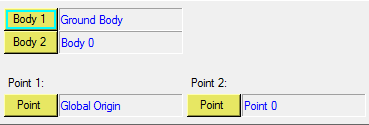
Entities can only be selected from an active collector. A collector is active when it is
enclosed in a blue rectangle, as shown in the image below. Figure 1. Body and point collectors
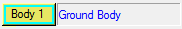
The label on the collector indicates the current entity type. Most collectors also display
the name of the current selected entity in the field next to it. If no entity is selected,
the field will display the label "Unresolved". Figure 2. Collector label
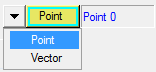
Some collectors have a collector switch that allows you to change the entity type from a
combo box. When the combo box is expanded, a list of available entity types is displayed.
Only one type of entity can be selected at a time. Figure 3. A collector with a combo box