Create and use your own symbol library.
You can provide the StarVision PRO tool a symbol library. This symbol library is an ASCII file that contains symbol shape definitions for cells used in the loaded design.
Map to Built-In Symbol Shapes
The following 'symbol' lines map the name patterns given in the second column to built-in logic gate symbols:
symbol and*    * AND   permute all
symbol buf*    * BUF
symbol nand*   * NAND  permute all
symbol nor*    * NOR   permute all
symbol not*    * INV
symbol or*     * OR    permute all
symbol xnor*   * XNOR  permute all
symbol xor*    * XOR   permute all
A mapping to the built-in multiplexer symbol looks like this:
symbol MUX* * MUX port SEL in.top
A mapping to a latch or dff symbol is expected to have 1 or 2 inputs, one clocked input, 1 or 2 outputs and maximal 1 top or bottom pin. The input marked as clk is always placed at the second input pin position. The inputs marked as top or bot are placed on the top respectively on the bottom of the symbol (control pins).
symbol DFF* * LATCH port CLK in.clk port SET in.top port RST in.bot
This is a mapping to a generic box:
symbol other* * GEN port C in.clk port SEL in.top
You can also specify a Boolean equation as the symbol type:
symbol xor     * BOOL Y a^b^c   permute all
symbol xa1     * BOOL Y (a^b)*c permute all
These symbols are for AND-OR, OR-AND, AND-XOR, OR-XOR, XOR-AND and XOR-OR combi gates. They are expected to have one output and n input pins. A symbol shape for the gate depends on the specified type; "type" must be a sequence of digits > 0 - each defines the number of inputs for a first-level sub-gate. The order of the input pins is important - e.g. for "AO(3211)", the first 3 input pins go to the first AND sub-gate, and the next 2 input pins go to the second AND sub-gate and the remaining 2 input pins go directly to the OR sub-gate. The sum of the digits must be equal to the number of input pins. Both input and output pins support the .neg pin option to create bubbled pins.
AO(type)
OA(type)
AX(type)
OX(type)
XA(type)
XO(type)
Convert Symbols Coming from Other Tools
The StarVision PRO download package contains symbol conversion utilities, a symbol viewer as well as a symbol editor and documentation of the symlib format.
There are two conversion tools:
-
Slibconv: a converter program that converts symbol shapes from the Synopsys symbol library format (slib file) to the Symlib Data Format.
-
Cadence2symlib: a exporter program that exports symbol shapes from Cadence to the Symlib Data Format.
The result from each of this conversion utilities is a symlib file. You can use the symedit tool to view the result of the conversion process.
Use symedit to either start from scratch creating symbols or use it to customize the result of one of the conversion utilities.
To overwrite a box with a nice symbol shape the name of the symbol must match the name of the module. Here is an example of the gl85 design which can be found in the demo directory.
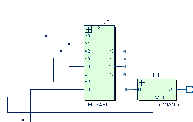
In the Schem window you can see a box for the module MUX4BIT:
Now you can provide a symbol library file to StarVision PRO in the file open dialog or on the command line. Here is an excerpt of a symlib file:
symbol MUX4BIT * DEF \
    port A0 left -loc -12 -90 0 -90 \
    pinattrdsp @name -lr -2 -92 10 \
    port A1 left -loc -12 -80 0 -80 \
    pinattrdsp @name -lr -2 -82 10 \
    ...
    port Y0 right -loc 52 -70 40 -70 \
    pinattrdsp @name -ll 42 -72 10 \
    ...
    permute {([A0,A1,A2,A3],[B0,B1,B2,B3])} \
    attrdsp @name -ll 20 -110 10 \
    attrdsp @cell -uc 20 -7 10 \
    fpath 0 -10 0 -100 40 -80 40 -30 0 -10
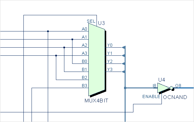
Now you can see the symbol shape in the Schem window.