The "Meta Attributes" control the visibility of attributes in the Schem and Cone windows.
The "Meta Attributes" are identified by the predefined names @nlv or @nlv:… — they are attached to the database root, to the Primitives and Modules and to the Primitives' and Modules' Ports and PortBuses.
Overview
This Document describes the "Meta Attributes" and how they control the display of ordinary database attributes. In addition to this meta attributes, the hide flags also control visibility in the schematic windows.
Those Meta Attributes can be set through the API when loading the database.
The Meta Attributes can be modified with ordinary attr commands — usually followed by a call to gui attribute changed to update the schematics.
If customer symbols are used (by specifying -symlib), then the symbols should define display locations (called attrdsp) for the Instance Attributes to be displayed.
Format String
Each "Meta Attribute" defines a format string that is displayed after replacing all occurrences of %xxx by the contents of attribute xxx.
As common to Tcl and other interpreters, the attribute name ends with the first special character or space.
Braces may be used to precisely define the end of the attribute name: that means, %{xx}x addresses the attribute xx, not xxx.
A double %% creates a single % character.
For backward compatibility, a $ character has the same meaning as the % character.
Newline characters (\n) can be used to create multi-line outputs, this is recommended to display multiple Instance attributes, one per line.
Conditional Expressions
Meta attributes may contain conditional expressions of the form:
?{<attr>{<then>}:{<else>}}
or
?{<attr><check><number>{<then>}:{<else>}}
where the :{<else>} part is optional.
The first conditional expression is replaced by the <then> part if the referenced attribute <attr> exists, otherwise it is replaced by the <else> part (if the <else> part is missing, an empty string is used).
The second conditional expression contains a <check> operator (one of <, =, !, >) and a floating point number <number>.
It is replaced by an empty string if the referenced attribute <attr> does not exist, it’s replaced by the <then> part if the attribute’s value fulfills the <check> condition (if the value if less (<), equal (=), not equal (!), or greater (>) than <number>), and it’s replaced by the <else> part if the condition is not met (if the <else> part is missing, an empty string is used).
The <then> and <else> parts of the conditional expression are themselves full expressions, including references to attributes, or even other conditional expressions.
Display Instance Attributes
The Meta Attribute @nlv at an Instance’s cellref (Primitive or Module) controls what is displayed at the built-in symbols (for customer symbols, see below).
Built-in symbols only define ONE general purpose display location for attributes — but newline characters can be used to separate lines to display multiple attributes.
This works identical for both Instances of Primitives and Instances of Modules (UML diagram).
One pseudo attribute name @cell@ is always defined to grant access to the Instance’s Primitive or Module name (however, if a @cell@ attribute exists, then the attribute is used).
Example
Assuming the Instance attributes are L=12u, W=24u and AS=8.3:
| Meta Attribute | Display in Schematic |
|---|---|
|
|
|
|
|
|
|
|
|
|
Instance Attributes at Customer Symbols
If customer symbols are used (e.g. with command line option -symlib), then the symbols should define display locations (called "attrdsp") for the instance name (called @name) and a general purpose display location for attributes (called @value for transistor level (Spice) devices — and @cell for gate level Primitives) as well as for Modules.
Here are two customer symbol examples (see "The Symlib Format" for more information):
symbol _RES_ * DEF device nonpolar \
    attrdsp @name -ll 10 0 12 \
    attrdsp @value -ul 10 3 12 \
    ....
symbol and2 * DEF \
    attrdsp @name -ll 5 -22 12 \
    attrdsp @cell -cl 5 22 10 \
    ....
Alternatively, the database root attribute @nlv:all could be set (to an arbitrary value) — to make all Instance attributes copied over to the schematic windows and those attributes with a dedicated display information (attrdsp) will get displayed (with some performance drawback for big circuits).
API Example
Here is an API example that sets or modifies the @nlv meta attribute at all NMOS and PMOS primitives:
set meta "L=%L\nW=%W\nA=%AS"
$db foreach primitive p {
    set func [$db primFuncOf $p]
    switch $func {
        "NMOS" -
        "PMOS" {
            $db attr $p set @nlv=$meta
        }
    }
}
The next API example just sets the @nlv:all database root attribute (see above):
$db attr -db set @nlv:all=1Display Pin Attributes
The Meta Attribute @nlv:pin at the database root controls what is displayed at the built-in symbol pins (for customer symbols, see below).
Built-in symbols only define ONE general purpose display location for pin attributes (newline characters can be used to display multiple pin attributes but because of space limitations, this is not recommended).
This works identical for both, Pin and PinBus objects (UML diagram).
Example
Assuming the Instance Pin attributes include delay=12.5 at pin A and delay=7.0 at pin B — and assuming the meta attribute @nlv:pin is set to %delay — then the table below shows what is displayed at pins A and B:
Set Meta Attribute @nlv:pin via API |
Pin | Display in Schematic |
|---|---|---|
|
|
|
|
|
Pin Attributes at Customer Symbols
If customer symbols are used (e.g. with command line option -symlib), then the symbols may define display locations (called pinattrdsp) for the pin name (called @name) and a general purpose display location for pin attributes (called @attr).
However, if pinattrdsp @name is not defined, then the pin name is not displayed, and if pinattrdsp @attr is not defined, then the @attr is displayed anyway, automatically placed close to the pin location (this means, a customer symbol may predefine @attr at the preferred location).
Here is a customer symbol example that defines @name and @attr for pins (see "The Symlib Format" for more information):
symbol enand4 * DEF \
    port O output -loc 55 0 47 0 \
    pinattrdsp @name -cr 52 -4 8i \
    port A input -loc -15 -30 0 -30 \
    pinattrdsp @name -cl -10 -35 8i \
    pinattrdsp @attr -cl -10 -30 8 \
    port B input -loc -15 -10 0 -10 \
    pinattrdsp @name -cl -10 -15 8i \
    pinattrdsp @attr -cl -10 -10 8 \
    port C input -loc -15 10 0 10 \
    pinattrdsp @name -cl -10 5 8i \
    pinattrdsp @attr -cl -10 10 8 \
    port D input -loc -15 30 0 30 \
    pinattrdsp @name -cl -10 25 8i \
    pinattrdsp @attr -cl -10 30 8 \
    ....
Display Port Attributes
The Meta Attribute @nlv:port at the database root controls what is displayed at the built-in IO connectors (for customer IO symbols, see below). IO connectors only define ONE general purpose display location for attributes — but newline characters (\n) can be used to display multiple attributes.
This works identical for both Port and PortBus objects (UML diagram).
Example
Assuming Port A's attributes include delay=3.7, Port B's attributes include delay=5.5, and PortBus DATA's attributes include delay=9.1 — and assuming the meta attribute @nlv:port is set to %delay ns — then the table below shows what is displayed at ports A, B and DATA:
Set Meta Attribute @nlv:port via API |
Port | Display in Schematic |
|---|---|---|
|
|
|
|
|
|
|
|
Port Attributes at Customer IO Symbols
If customer IO symbols are used (e.g. with command line option -symlib), then the symbols should define display locations (called attrdsp) for the port name (called @name) and a general purpose display location for attributes (called @attr).
Here are three complete customer IO symbol examples (the names are fixed for input, output and bidir IO connector):
symbol sv_extInOutPort * DEF \
        attrdsp @name -cl 22 0 10 \
        attrdsp @attr -ll 0 -5 10 \
        port {} input -loc 0 0 0 0 \
        path 15 5 15 -5 20 0 15 5 \
        path 5 5 0 0 5 -5 5 5 \
        path 15 0 5 0
symbol sv_extInPort * DEF \
        attrdsp @name -cr -17 0 10 \
        attrdsp @attr -lr 0 -5 10 \
        port {} output -loc 0 0 0 0 \
        path -15 5 -15 -5 -10 0 -15 5 \
        path -10 0 0 0
symbol sv_extOutPort * DEF \
        attrdsp @name -cl 22 0 10 \
        attrdsp @attr -ll 0 -5 10 \
        port {} input -loc 0 0 0 0 \
        path 15 5 15 -5 20 0 15 5 \
        path 15 0 0 0
Display Net Attributes
The Meta Attribute @nlv:net at the database root controls what attributes are displayed at the Net and NetBus objects.
Those attributes are only visible, if they are enabled in the Preferences dialog at Display > Net Attributes at wire.
For power and ground nets, the Meta Attributes @nlv:powernet and @nlv:groundnet at the database root additionally control what attributes are displayed at the Net’s power or ground stubs.
Those attributes are only visible, if they are enabled in the Preferences dialog at Display > Power/Ground Label.
One pseudo attribute name netname is always defined to grant access to the Net name (however, if a netname attribute exists, then the attribute is used).
Example
Assuming Net A is a power net and its attributes include width=3.7, voltage=1.9 and crit=420 — and assuming the meta attributes @nlv:net and @nlv:powernet are set as in the table below — then the table below shows what is displayed at the net and at the net’s power stubs:
| Set Meta Attributes via API | Display in Schematic | |
|---|---|---|
|
At Net |
At Power Stubs |
|
|
|
Attributes at Virtual Objects
To set a format string for a virtual OID, the @nlv:virtual meta attribute can be used.
Formatting Attributes
In addition to the attribute name and value an @format attribute at the same object can be added to specify the color and font scale of the displayed attribute.
It allows to specify a foreground and background color and a font scaling factor to overwrite the default foreground color of the attribute and scale the font size to the given value.
The syntax of this option is:
(?+?<foreground>,-|<background>,<fontscale>)
The <foreground> and <background> values must be in #RRGGBB color format.
The <fontscale> is a floating point number that specifies a factor for the text height (e.g. 1.5 makes it 50% bigger; 0.7 makes it 30% smaller).
The optional leading + gives the <foreground> color priority over the highlight colors.
A - as background color defines a transparent background.
Display Graphical Marks
In addition to the text attributes special built-in graphical attributes (marks) can be displayed at Net/NetBus, Pin/PinBus and Port/PortBus objects.
The Meta Attribute @nlv:marks at the database root controls what graphical marks are displayed.
Those attributes are only visible if they are enabled in the Preferences dialog at Display > Graphical Marks.
The following mark types are supported:
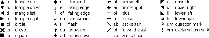
The format of a graphical mark attribute value is a white-space separated list of single mark definitions containing the mark type and a format string.
<name>=<type>(<color>) <type>(<color>)
<name>=<type>(<color>,<bgcolor>) ...
<name>=<type>(<color>,,<ratio>) ...
<name> is the mark identifier; in order to display this mark, the DB root attribute @nlv:marks=%<name> has to be set.
The <bgcolor> and <ratio> items in the format are optional, but the comma must be given, if <bgcolor> is omitted but a <ratio> is present.
Two (or more) marks can optionally be combined into more complex shapes by concatenating them with a & character like this:
<name>=<type>(<color>)&<type>(<color>)
<type> is one of the predefined mark types.
<color> is a color definition to set the (foreground) color of the mark — optionally prefixed by a + character to indicate priority over the highlight and selection colors.
<bgcolor> is an optional color definition to set the background color for this individual mark.
If not specified, the background will be transparent.
<ratio> is an optional floating point number which specifies the width:height aspect ratio of the mark.
A value of 2.0 will display the mark twice as wide as the default size, with a value of 0.5 only half the default size is used as width.
The height is always the internal default marksize and cannot be changed.
When <ratio> is omitted, a default value of 1.0 is used internally.
The marks are displayed in the same left-to-right order as specified in the attribute value.
Example
Assuming the Instance Pin attributes include edge=er(#ff0000) at pin A and edge=ef(#00ff00) at pin B — and assuming the meta attribute @nlv:marks is set to %edge — then the table below shows what is displayed at pins A and B:
| Set Meta Attributes | Pin | Display in Schematic |
|---|---|---|
|
|
Rising edge symbol (colored red) |
|
Falling edge symbol (colored green) |