Same Type Check/Comparison
Comparison for Same-Type Data.
Data Reading
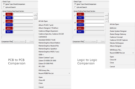
Figure 1.
- Same Type Check/Comparison: Compare the same type data, such as PCB design to PCB design or schematic and schematic.
- Import two designs into this column and import files.
- Using the menu, All Job Open, you can import multi-design files at the same time.
- Import ECAD files directly.
- Import design among recently used list.
Processing Window Menu
PollEx Cross Probe Classifies Setting and Result. Using the Setting tab, you can read various designs and can compare the differences from design’s change. Using the Result tab, you can check the design by PCB Merge, Exe All, and so on.
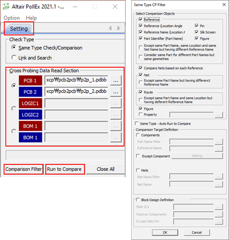
Figure 2.
- Cross Probing Data Read Section: After reading designs, you can see design paths and other menus are activated.
- Compare Filter: Set comparing conditions. Using the Display Option dialog you can edit the comparison conditions.
- Run Compare: Start comparing two designs.
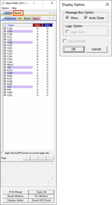
Figure 3. - PCB Merge: Merge two PCB designs into one. You can easily detect what differences are in the design.
- Exe All: Launch necessary applications.
- Using the Reset Window menu, you can place three different window applications on the screen.
- Fix Window: Keeps the window’s status and supports functions to fix the window.
- Display Option b. After reading PCB designs, Message Box Option is activated. The message box displays according to setting conditions. After reading schematic designs, Logic Sync is activated. It can be used to synchronize two schematic viewers’ status.
- Export MS Excel menu has two types such as Basic Excel Format and Add to specified MS/Excel File.
- Basic Excel Format: Export current results to the MS/Excel sheet. If you want to
attach images at each comparing result, set this condition in the user
information setting. Activate Include Result Image in the environment setting to
include images in MS/Excel.
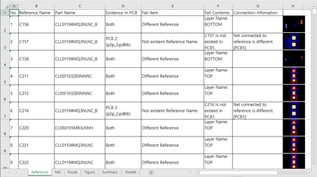
Figure 4. - Add to specified MS/Excel File: For accumulating data, after you export MS Excel
using Basic Excel Format, export MS Excel based on basic excel.
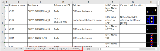
Figure 5.
Run Compare - PCB to PCB
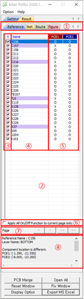
Figure 6.
- Classification for comparing results. PollEx Cross Probe compares PCB design to PCB design for components (reference designator), net, routing pattern, figure (non-electrical geometries) and critical pattern that you defined in environment.
- PollEx Cross Probe shows each classification’s results.
- Select target items that will be exported to MS/Excel sheet.
- Target objects’ name in PCB design. This list shows changed items. Both existing cases show white color. Existing items in PCB1 only show pink color. Existing items in PCB2 only show purple color.
- PollEx Cross Probe compares the differences from PCB designs’ change. It shows existence in each design regarding changes. For an existing case, PollEx Cross Probe shows “O” mark and non-existing case it shows “X” mark.
- When selecting the “V” section above ③, you can select/clear an item in the whole page. If selecting the “V” section above ③ after you checks ⑥, you can select only the items on the current page, not the whole page on/off.
- If the number of comparing result items is a huge case, you can show them into different pages. The maximum number of showing items in one page is 100.
- Each selected item’s detailed description.
Result Review - PCB to PCB
Click Open All (launches all applications) and select each comparing result item. PollEx Cross Probe highlights each item on two different PollEx PCB tools.
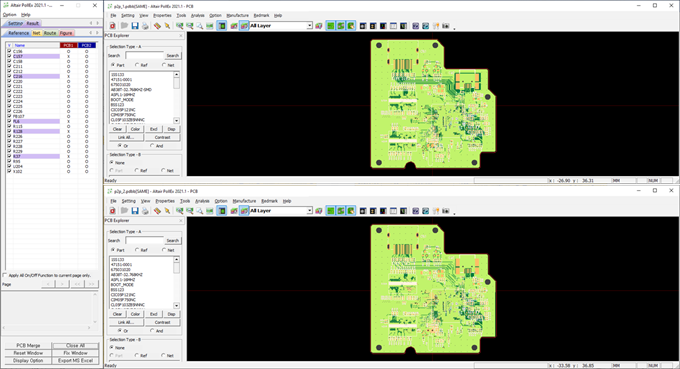
Figure 7.
PCB Merge
If PollEx Cross Probe compares two PCB designs, checking the difference manually is confusing because many cases’ difference may be a minute scale. To distinguish them in the same screen, you can use the PCB merge function in PollEx Cross Probe.
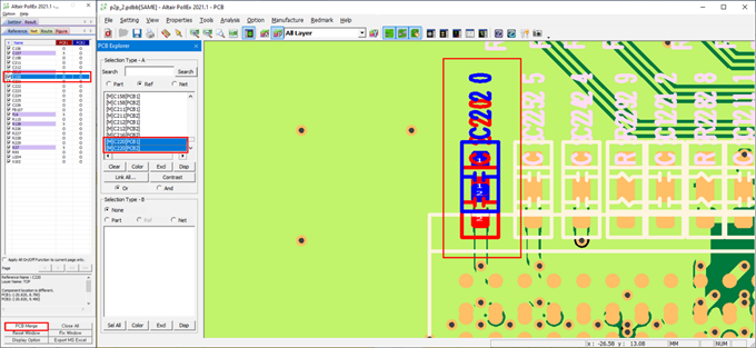
Figure 8.
Click PCB Merge to merge two PCB designs into one. A new PollEx PCB, PCB Explorer function is automatically linked and contains checking results. In the PCB Explorer window, select each item. The Selected item’s objects are highlighted with different colors. You can distinguish object sources with colors, red and blue. The red color object means it comes from PCB design first and the blue object comes from PCB design second. To view objects below, press Tab.
Run Compare - Logic to Logic
Compare two schematic designs. Set the comparing filter for schematic comparing and click Compare Filter.
- Net List: Compare the netlist between schematics.
- Reference List: Compare the reference list between schematics.
- Option: Search object sheet by sheet.
- Location in Sheet: Compare geometries in sheets.
- Shape of Symbol: Compare shape of symbols.
- Property: Compare properties of objects.
After comparing two schematic designs, merging two schematic designs are impossible. You can synchronize two schematic viewers’ status. Moving or zooming in one application is applicable same as to the other application.
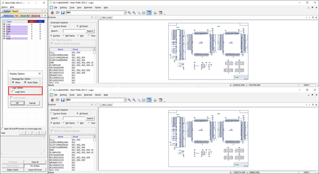
Figure 9.