New Layout
This option allows the user to create a new reflectarray or transmitarray layout. Three elements are required to create a reflectarray layout:
- Database
The database contains all the geometric cells available for the reflect array generation, together with their field values by frequencies and components. It must have been created by using the Periodical Structures module (see Annex 1: Creating a Reflectarray Database for an example).
- Target surfaces.
Single layer that defines the real shape of the top reflect array layout the upper interface of the reflect array will be placed on the target surfaces, and the next interfaces will be automatically generated. Both planar and curved surfaces are allowed, but the generation for planar surfaces is faster. In the case of using curved surfaces, a soft curvature is recommended.
The layout is generated by considering a planar grid on the current XY system (see Reference Plane) and projecting it onto the target surfaces with the reference Z direction, so it is important to have a good agreement between the surfaces orientation and the reference system.
After the layout generation, the original surfaces are deleted.
- Cell Selection Function.
The best available cell is assigned at a point of the grid on the real geometry, considering as the best cell the one that provides the closest phase to the given by the selection function.
The user may set its own selection function programmed in Java. The next variables can be read from a custom function, all of them with their name starting with the "$" character, and obtained from the reflectarray generation parameters:
- $freq Working frequency, given in Hz.
- $x, $y, $z Cell position where the function is evaluated.
- $focusX, $focusY, $focusZ Focus position.
- $theta, $phi main beam direction, where the reflectarray must be pointing to.
The program function has to return a double value corresponding to the optimal phase at the given point, in degrees.
Include the customized functions in the /functions/ directory corresponding to the installation path.
See further information about the custom functions programmatic in User Functions.
The fields for the layout generation are explained in the following.
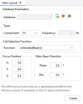
Figure 1. New Layout Parameters tab
- Database: Shows the selected database file to create the new
layout. With the
 button a file chooser window will
prompt the user to add a database file.
button a file chooser window will
prompt the user to add a database file. Opens a database information tab on
the main panel of the application. With this button, it is possible to visualize all
the relevant parameters of the database: cell dimensions, cell replications, material
considered, skew angle, geometrical models, plots of the phase cells,…The
Opens a database information tab on
the main panel of the application. With this button, it is possible to visualize all
the relevant parameters of the database: cell dimensions, cell replications, material
considered, skew angle, geometrical models, plots of the phase cells,…The  button detaches the specified database
from the layout.
button detaches the specified database
from the layout. - Component: Allows the user to select the desired polarization component of the database to generate the layout.
- Frequency: Allows the user to select the desired frequency of the database to generate the layout.
- Function: Allows the user to select the desired user function to assign one cell of the database to every position of the base geometry.
- Focus Position: Allows the user to define the point of the source.
- Main Bean Direction: Allows the user to define the output direction of the main beam.
Is possible to specify more than one database in order to create more complex layouts. In order to do so, user must specify the parameters of each database file separately.
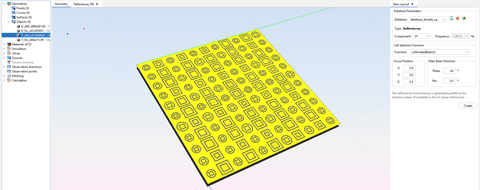
Figure 2. Multi database ReflectArray Layout