Create a Local System
Create a local coordinate system and apply it to a load such as a force or support.
-
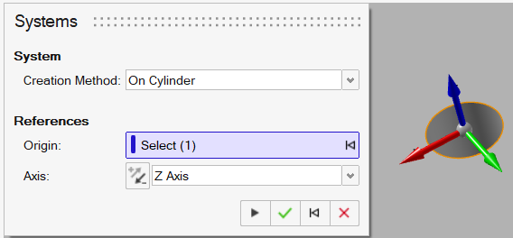
On the Home ribbon, click the Systems tool.

The guide panel appears.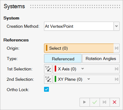
-
Select a Creation Method you want to use to create a
system.
Option Description At Vertex/Point Use the Origin collector to select an origin point. On Cylinder Use the Origin collector to click the cylindrical face or circular edge of a cylinder and use the Axis dropdown to select the axis that aligns with the center of the cylinder. By default, the origin of the system is displayed at the center of the circle or the centroid of the cylinder.
On Edge Use the Origin collector to click an edge. You can specify the Ratio to position the origin along the edge and use the 1st Selection and Second Selection dropdowns to select the axes. Three Planes Use the Planes collector to click three orthogonal planes. The origin is the intersection of the selected planes, and the 1st Selection and Second Selection dropdowns select the axes. On Face Use the Origin collector to click the face where you want to position the origin and use the Axis dropdown to choose the axis that is perpendicular to the selected face at that point. From System Use the Origin collector to select the vertex or point that you want to use as the origin, and use the the System collector to select an existing (source) system the new system will match. If you update the source system, the new system is updated to match. Absolute Click to position the origin. The global XYZ coordinates are populated based on the origin you click, and you can use the Origin and Euler Angles controls to adjust the orientation. -
Select the origin of the system. By default the Origin
collector is turned on.
Note: By default, a system is oriented along global XYZ.
- If On Edge is selected as the creation method, enter a Ratio to set the position of the origin. For example, a Ratio of .5 sets the origin to the midpoint of the selected edge.
-
Select the type of system you want to create.
- Select Referenced to create references to geometric entities in the model, such as vertices/points, edges, and faces.
- Select Rotation Angles to define a system based on the rotation angles.
-
Select the references or rotation angles for the system. To translate or rotate
the system:
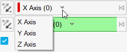
- If Referenced is selected, use the 1st
Selection collector to select the X, Y, or Z axis as the
first reference. You can use the down arrow to select which axis you
want to use.
 If Referenced is selected, use the 2nd Selection collector to select the plane you want to use as the second reference. You can use the down arrow to select which plane you want to use.
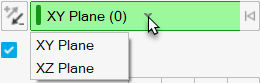
Tip: Select Ortho Lock to allow projections to find the intersection of the 1st Selection and 2nd Selection in case the second selection breaks. When Ortho Lock is not selected, Inspire will not allow users to create systems if the 2nd selection breaks orthogonality.- If Rotation Angles is selected, enter the θx, θy, θz Euler Angles to rotate the system.
- If Referenced is selected, use the 1st
Selection collector to select the X, Y, or Z axis as the
first reference. You can use the down arrow to select which axis you
want to use.
-
Right-click and mouse through the check mark to exit, or double-right-click.
The new system is added to the References folder in the Model Browser.
Tip:
- You can create cylindrical coordinate systems using the On
Cylinder creation method. Use the
Origin collector to select the cylinder, and use
the Axis dropdown to select which axis corresponds to
the center of the cylinder.
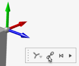
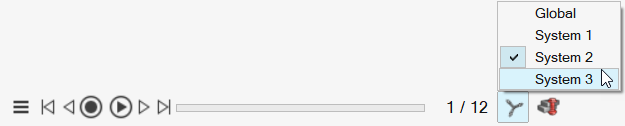
- When viewing animation, you can choose among a model's systems using the
System button in the Animation toolbar.
- Displacement components can be reviewed in local systems using the Animation
toolbar.Tip: To break reference and convert to an absolute system, right-click a system in the Construction History window and select Break Reference or double-click the system and click Break Reference in the microdialog: