Bushings can be created between two set of surfaces of two parts or a single set of
surfaces of a single part to ground. You need to define at least one linear or rotational
stiffness. Mass is optional.
You can create a bushing with the default properties or
create a bushing with the same properties as the previously selected bushing.
-
On the Structures or Motion ribbon, select the Bushings
tool.

-
Choose the type of bushing to create:
- Part to Part (default): Create a bushing between
selected surfaces of a pair of parts.
- Part to Ground: Create a bushing between selected
surfaces of a single part to ground.
-
Do one of the following:
- To create a bushing with the default properties, select the surfaces of
two parts between which you want to create a bushing.
- To create a bushing with the same properties as the previously selected
bushing, select a surface.
Note: While holding down Ctrl,
click to multi-select and deselect.
-
On the Stiffness, Damping, and
Preload tabs, you can do the following:
Note: Damping, and
Preload are only available if you opened
Bushings from the Motion ribbon.
-
Choose between orthotropic or isotropic stiffness:
- To apply orthotropic stiffness to the bushing (use different
stiffness, damping, or preload values for each direction,) in
the guide panel, turn on
Orthotropic.
- To apply isotropic stiffness to the bushing, turn off this
option.
-
Enter at least one linear stiffness property or one rotational
stiffness property.
| |
If you applied orthrotropic stiffness |
If you applied isotropic stiffness |
| To define linear stiffness |
Enter TX,
TY,
TZ. |
Enter T(X, Y, Z). |
| To define rotational stiffness |
Enter RX,
RY,
RZ. |
Enter R(X, Y, Z). |
-
Optional: Enter at least one linear damping property
or one rotational damping property.
| |
If you applied orthrotropic damping |
If you applied isotropic damping |
Notes |
| To define linear damping |
Enter TX,
TY,
TZ. |
Enter T(X, Y, Z). |
This option is only available for Motion. |
| To define rotational damping |
Enter RX,
RY,
RZ. |
Enter R(X, Y, Z). |
This option is only available for Motion. |
-
Optional: Enter at least one linear or rotational
preload property.
| |
If you applied orthrotropic preload |
If you applied isotropic preload |
Notes |
| To define linear preload |
Enter TX,
TY,
TZ. |
Enter T(X, Y, Z). |
This option is only available for Motion. |
| To define rotational preload |
Enter RX,
RY,
RZ. |
Enter R(X, Y, Z) |
This option is only available for Motion. |
-
On the Inertia tab, enter the
following:
Note: The Inertia tab is only
available if you opened Bushings from the
Structures ribbon.
- Mass: Enter the bushing's mass.
- Ixx: Enter the moment of inertia about the axis
oriented as global x passing through the center of mass
- Iyy: Enter the moment of inertia about the axis
oriented as global y passing through the center of mass
- Izz: Enter the moment of inertia about the axis
oriented as global z passing through the center of mass
-
Click Create the Bushing
 .
.
-
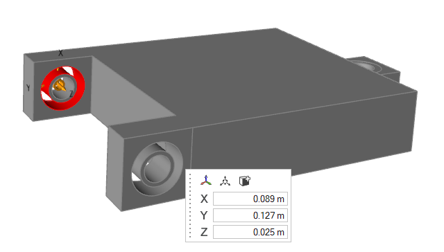
In the microdialog, you have the following options:
| Option |
Description |
Align to Global Axes

|
Align to the global axes. |
Move

|
Translate or rotate using the Move tool. |
Add/Remove

|
Add/remove faces from the selected bushings. |
| Set Origin X |
Set the origin coordinate in the X direction. |
| Set Origin Y |
Set the origin coordinate in the Y direction. |
| Set Origin Z |
Set the origin coordinate in the Z direction. |
-
To create more bushings, repeat Steps 2–7.
-
Right-click and mouse through the check mark to exit, or double-right-click.