OS-E: 6010 Rotor Unbalance using Modal Frequency Response Analysis
This example is used to find the unbalance frequency in the Rotor using modal frequency response analysis in OptiStruct.
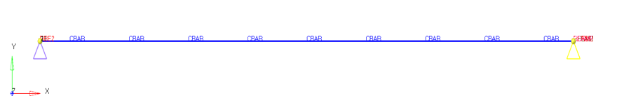
Figure 1. FE Model
Model Files
Before you begin, copy the file(s) used in this example to
your working directory.
Model Description
This example consists of two coaxial rotors modeled using 1D elements, one end of each
rotor is constrained, the same end is attached to stator using rigid elements, and on the
other end is attached to the stator through Spring and Damper elements. Dynamic loading
condition are applied to the rotors with phase difference and a relative spin between the
two rotors are also defined. Multiple methods are used to compare the unbalance in the
rotors using modal frequency response analysis.
| FE Model | 1D Elements |
|
| Material | Material MAT1 | Rotor:
|
| Reference Guide Entries | Keywords | RGYRO, ROTORG, RSPINR, DDVAL, DLOAD, DAREA, UNBALNC, DPHASE, RLOAD2, FREQ1, EIGRL |
Results
- Subcase
- 1st Peak Frequency
- DLOAD
- 422.60 Hz
- Unbalance Force
- 422.60 Hz
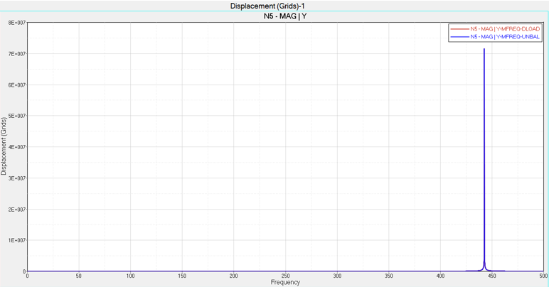
Figure 2. Displacement versus Frequency Plot at the Grid #5