OS-E: 5010 High Frequency Electromagnetic and Thermal Analysis of Antenna
Demonstrates Feko and OptiStruct coupling through an analyze of an antenna model for radiation and heat transfer.
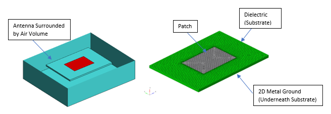
Figure 1. Geometry of Pin Fed Patch Antenna and FE Model
| Steps | Output |
|---|---|
| The .epl and .nas files are obtained using EG (End of Geometry) from EDITFEKO. | |
| Add the update.py file to the Compose Installation directory in your
machine (example: C:\Program
Files\Altair\20xx\Compose20xx.y). Run the
.oml file in Compose and input the files generated
by Feko in the toolbar that
appears as:
|
Compose will write a new .nas file and the heat-loss_2P93000000E009.fem file. |
| Open OptiStruct and input the above generated Antenna2.nas file and perform Heat Transfer Analysis. | Results in heat lose, due to radiation from antenna. |
Model Files
- Feko files
- Antenna.epl and Antenna.nas
- Compose file
- map.oml
- Map file
- Antenna.map
- Python Script
- update.py
- OptiStruct files
- Antenna2.nas and heat-loss_2P93000000E009.fem (these files can be generated by running the map.oml file in Compose)
Model Description
The objective is to compute the electromagnetic radiation pattern of the antenna in Feko and to analyze the heat generated, due to electromagnetism in OptiStruct. Altair Compose Script is utilized to modulate the Feko results and fed input to OptiStruct.
The device used (Figure 1) is a Pin-fed Patch Antenna comprised of metal patch, dielectric material connected to metal ground and surrounded by air. The patch is fed by a finite-element line port between the ground and the patch.
The input frequency is 2.93 GHz and the source power is 30 W. Of the 30 W, 3.2 W is reflected to the source (mismatch loss), 21.5 W is radiated, 1.7 W is lost in the metallic faces and 3.6 W is lost in the substrate. The last two electromagnetic losses are transformed into heat. This heat loss is analyzed in OptiStruct.
- Substrate
- Value
- Relative Dielectric Permittivity
- 2.2
- Loss Tangent
- 0.01
- Size
- 7 x 10 x 0.287 cm3
- Metal Patch
- Value
- Relative Dielectric Permittivity
- 2.2
- Electric Conductivity
- 1E+06 S/m
- Size
- 3.118 x 4.665 cm2
- Thickness
- 35E-06 m
- Ground
- Value
- Electric Conductivity
- 1E+06 S/m
- Thickness
- 35E-06 m
- Element Type
- CTETRA4
- Material: Copper (MAT4)
- Thermal Conductivity
- 401.0 (W/m)-K
- Specified Heat Capacity
- 385 (J/kg)-K
- Density
- 8960 kg/m3
- Free Convection Heat Transfer Coefficient
- 25.0 W/m2
- Material: Dielectric (MAT4)
- Thermal Conductivity
- 0.3 (W/m)-K
- Specified Heat Capacity
- 300 (J/kg)-K
- Density
- 1000 kg/m3
- Free Convection Heat Transfer Coefficient
- 20.0 W/m2
Results
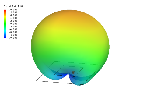
Figure 2. Antenna's Far-field Radiation Pattern
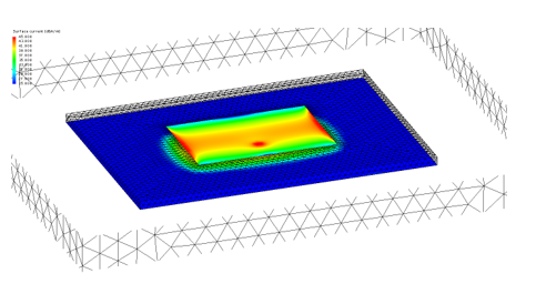
Figure 3. Surface Currents in the Metals
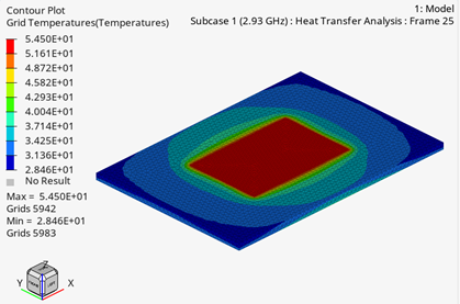
Figure 4. Final Temperature Distribution