Method 2: PCB Cooling Channel using Inlet Pressure and Outlet Pressure
Launch HyperWorks
- Launch Altair HyperWorks.
- In the New Session window, select HyperMesh.
- For Profile, select OptiStruct.
- Click Create New Session.
Import the Model
- On the menu bar, select .
- Navigate to and select PCB.hm.
- Click Import.
Set Up the Model
Define Material 1
Note: If the model loads outside of the modeling window,
press F to fit to window.
- In the Model Browser, right-click and select .
- For Name, enter material1.
- For Card Image, select MAT1 from the drop-down menu.
-
Enter the following material properties:
- For E, enter 210000
- For NU (Poisson's ratio), enter 0.3.
- For RHO, enter 7.85e-09.
-
Select the MAT4 check box and enter the following
properties:
- For K (thermal conductivity), enter 44.0
- For CP, enter 460000000.
- For RHO, enter 7.8e-09.
- Click Close.
Define Material 2
- In the Model Browser, right-click and select .
- For Name, enter material2.
- For Card Image, select MAT1 from the drop-down menu.
-
Enter the following material properties:
- For E, enter 210000
- For NU (Poisson's ratio), enter 0.3.
- For RHO, enter 7.85e-09.
-
Select the MAT4 check box and enter the following
properties:
- For K (thermal conductivity), enter 44.0
- For CP, enter 460000000.
- For RHO, enter 7.8e-09.
-
Select the DARCY check box and enter the following fluid
material properties:
- KAPPA, enter 0.1.
- For MU, enter 1e-09.
- For K, enter 0.598.
- For CP, enter 4183000000.
- For RHO, enter 1e-09.
- Click Close.
Define Property 1
- In the Model Browser, double-click on Properties to open the Property Browser.
- In the browser, select property1.
- For Card Image, select PSHELL from the drop-down menu.
-
For Material, select Unspecified >
 to open advanced selection.
- In the dialog, select material2 from the list.
- Click OK.
- For T (thickness), enter 0.5.
- Click Close.
Define Property 2
- In the Property Browser, select property2.
- For Card Image, select PSHELL from the drop-down menu.
-
For Material, select Unspecified > to open advanced selection.
- In the dialog, select material1 from the list.
- Click OK.
- For T (thickness), enter 0.5.
- Click Close.
Assign a Property to a Component
-
For Property, select Unspecified > to open advanced selection.
Apply Loads and Boundary Conditions
Apply Heat Flux
-
On the ribbon, select the Flux tool.

Figure 1.
Create the Inlet Node Set
-
For Entities, select nodes 131 to 151 as shown in Figure 2.
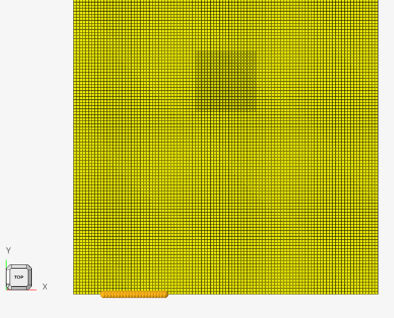
Figure 2.
Create the Outlet Node Set
-
For Entities, select nodes 191 to 211 as shown in Figure 3.
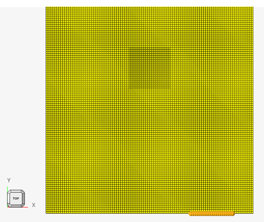
Figure 3.
Assign Thermal Boundary Conditions
-
On the ribbon, select the Temp Loads tool.
Figure 4. -
From the dialog, click nodes > and select by set.
Create Inlet Pressure and Outlet Pressure
- In the Model Browser, right-click and select .
- For Type, select SPCP from the drop-down menu.
-
For GSETID, select Unspecified > to open advanced selection.
- In the dialog, select inlet.
- For D, enter 0.1001.
-
Create a second load for outlet pressure.
- For Type, select SPCP from the drop-down menu.
-
For GSETID, select Unspecified > to open advanced selection.
- In the dialog, select outlet.
- For D, enter 0.1.
Create a Subcase
- In the Model Browser, right-click and select .
- For name, enter CPU loading.
- For Analysis Type, select Heat Transfer (Steady State) from the drop-down menu.
-
For the following selections, use Unspecified > to open advanced selection.
- For SPC, specify auto1.
- For LOAD, specify auto1.
- For SPCP, specify auto1.
Set Up the Optimization
Create the Topology Design Space
-
On the ribbon, select Topology.
Figure 5. -
From List of Properties, select Unspecified > to open advanced selection.
Create Responses
-
On the ribbon, select Responses.
Figure 6.
Create the Objective
-
On the ribbon, select Objectives.
Figure 7. -
For Response Id, select Unspecified > to open advanced selection.
Create Constraints
-
On the ribbon, select Constraints.
Figure 8. -
For Response, select Unspecified > to open advanced selection.
Run the Optimization
View the Results
-
HyperView, select Contour
 .
.
-
Click Apply.
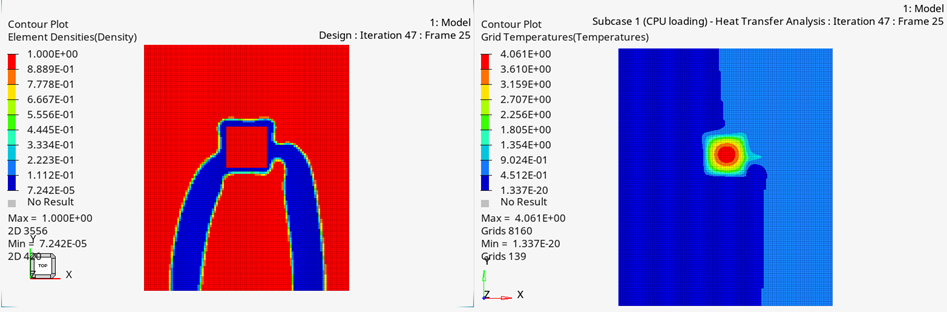 Figure 9.