OS-T: 1390 Pretensioned Bolt Analysis of an IC Engine Cylinder Head, Gasket and Engine Block System
This tutorial outlines the procedure to perform both 1D and 3D pretensioned bolt analysis on a section of an IC Engine. The pretensioned analysis is conducted to measure the response of a system consisting of the cylinder head, gasket and engine block connected by four head bolts subjected to a pretension force of 4500 N each.
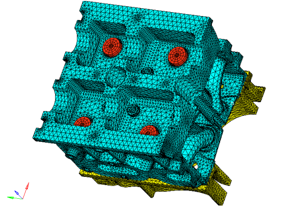
Figure 1. Model Showing the Cylinder Head, Engine Block and Head Bolts
The model consists of eight predefined components along with their corresponding property and material allocations. A contact surface (PT_Surf) has been defined, which is used for 3D pretensioning of an existing pretension surface. The pretension sections for 1D pretensioning have also been created on two of the four bolts and the sectioned bolts are reconnected using 1D beam elements (via rigids). A predefined visualization aid is also available under View, which allows you to easily look at the pretensioned sections of the four bolts. Contact surfaces and Contact Interfaces (TYPE=FREEZE) between the various parts have also been created so you can focus on the Pretensioning aspect of the tutorial.
Many engineering assemblies are put together using bolts, which are usually pretensioned before application of working loads. A typical sequence is described below. For further detailed information, refer to Pretensioned Bolt Analysis in the User Guide.
In Step 1, upon preliminary assembly of the structure, the nuts on respective bolts are tightened, usually by applying prescribed torque (which translates into prescribed tension force according to the pitch of the thread).
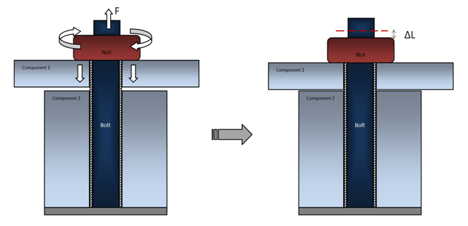
Figure 2. Step 1 of Pretensioned Assembly. Application of Pretensioning Loads
- Pretensioning actually shortens the working part of the bolt by removing a certain length of the bolt from the active structure (in reality this segment slides through the nut, yet the net effect is the shortening of the working length of the bolt). At the same time the bolt stretches, since now the smaller effective length of the bolt material has to span the distance from the bolt mount to the nut.
- Calculation of each bolt's shortening , due to applied forces F, requires FEA solution of the entire model with the pretensioning forces applied. This is because the amount of nut movement, due to given force depends on the compliance of the bolts, of the assembly being bolted and is also affected by cross-interaction between multiple bolts being pretensioned.
At the end of Step 1, the amount of shortening for each bolt is established and "locked", simply by leaving the nuts at the position that they reached during the pretensioning step.
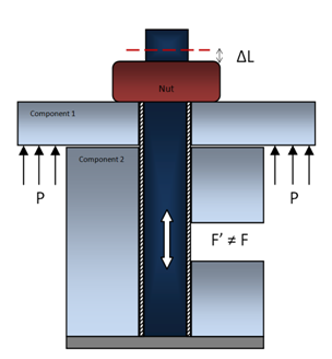
Figure 3. Step 2 of Pretensioned Assembly. Application of Working Loads with 'Locked' Bolt Shortening